Microwave radar sensing ceiling lamp

A technology of microwave radar and ceiling lamps, which is applied in the direction of lamp circuit layout, lighting and heating equipment, electrical components, etc., can solve the problems of waste of resources, short service life, high cost, etc., and achieve high utilization rate, long service life and low power consumption. low volume effect

Inactive Publication Date: 2015-04-01
JIANGSU MINGYU NEW ENERGY RESOURCES
View PDF0 Cites 2 Cited by
  • Summary
  • Abstract
  • Description
  • Claims
  • Application Information

AI Technical Summary

Problems solved by technology

[0002] Due to the advantages of energy saving, high brightness, no mercury, no infrared, no ultraviolet, no electromagnetic interference, no thermal effect, no radiation, no flicker phenomenon and many other advantages of LED lights, it has been widely used in hotels, conference rooms, factories or offices, commercial Uses, residential or public facilities, schools, hospitals where energy-saving and high color rendering index lighting are required, there are many radar sensor lights on the market, which are large in size, high in cost, waste of resources, uneven in light, and cannot be used for a long time. short lifespan, needs improvement

Method used


Image

  • Microwave radar sensing ceiling lamp
  • Microwave radar sensing ceiling lamp

Examples


Embodiment Construction

[0017] The present invention will be further explained below in conjunction with the accompanying drawings and specific embodiments. It should be understood that the following specific embodiments are only used to illustrate the present invention and are not intended to limit the scope of the present invention. It should be noted that the words "front", "rear", "left", "right", "upper" and "lower" used in the following description refer to the directions in the drawings, and the words "inner" and "outer ” refer to directions towards or away from the geometric center of a particular part, respectively.

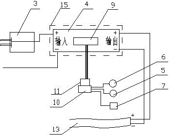
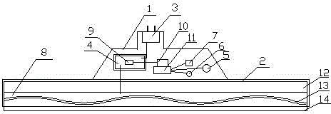
[0018] As shown in the figure, a microwave radar induction ceiling lamp according to the present invention includes a casing, a power input lamp holder 3, a power board 4, an induction head 5, a photosensitive resistor 6, a transmitting device, and a lamp 8. The casing is divided into a power supply The shell 1 and the lamp shell 2, the power input lamp holder 3 is connected to...


PUM


Abstract

The invention discloses a microwave radar sensing ceiling lamp. A shell is divided into a power supply shell and a lamp shell, a power input lamp cap is connected with the input end of a power supply board, the output end of the power supply board is connected with a lamp, the power supply board is provided with a driving power supply, the driving power supply is connected with a transmitting device, the transmitting device comprises a signal transmitter and a signal amplifier, and is connected with a sensor and a photoresistor, the lamp comprises a light guide plate, a light bar and an emergent light surface, the light bar is arranged between the light guide plate and the emergent light surface, the emergent light surface is a laser-dotted PMMA (polymethyl methacrylate) board, the power input lamp cap, the power supply board, the sensor, the photoresistor and the transmitting device are arranged in the power supply shell, the light guide plate and the light bar are arranged in the lamp shell, and the emergent light surface is clamped with the lamp shell. The microwave radar sensing ceiling lamp is reasonable in structure and can automatically detect the moving state of surrounding objects by utilizing the Doppler effect principle, the operating state can be intelligently adjusted, electricity consumption is low, resources are saved, the utilization rate of beads is increased, and the microwave radar sensing ceiling lamp can be used for a long time, and has a long service life.

Description

technical field [0001] The invention belongs to the technical field of lamps, and in particular relates to a microwave radar induction ceiling lamp. Background technique [0002] Due to the many advantages of LED lamps such as energy saving, high brightness, no mercury, no infrared rays, no ultraviolet rays, no electromagnetic interference, no thermal effect, no radiation, no stroboscopic phenomenon, etc., they have been widely used in hotels, conference rooms, factories or offices, and businesses. Uses, residential or public facilities, schools, hospitals where energy-saving and high color rendering index lighting are required, there are many radar sensor lights on the market, which are large in size, high in cost, waste of resources, uneven in light, and cannot be used for a long time. The lifespan is short and needs improvement. Contents of the invention [0003] In order to solve the above problems, the present invention discloses a microwave radar induction ceili...

Claims


Application Information

Patent Timeline
Patent Type & Authority Applications(China)
IPC IPC(8): F21S8/04F21V23/02F21V23/06H05B37/02F21Y103/00
CPCF21S8/04F21V23/023F21V23/06F21Y2103/00H05B47/11Y02B20/40
Inventor 王杏文王明杨定标郑竹琴
Owner JIANGSU MINGYU NEW ENERGY RESOURCES
Why Eureka
Try Eureka