
Three-axis structure and manufacturing process of micro inertial measurement unit based on ltcc process

A technology of micro-inertial measurement and manufacturing process, which is applied in the direction of measuring devices, navigation through speed/acceleration measurement, instruments, etc., and can solve unreliability and noise of circuit connection, large extra error output of accelerometer, large three-dimensional structure size, etc. problems, to achieve strong anti-external electromagnetic interference performance, reduced transmission loss and crosstalk, and good heat dissipation performance

Active Publication Date: 2017-03-15
EAST CHINA INST OF OPTOELECTRONICS INTEGRATEDDEVICE
View PDF9 Cites 0 Cited by
  • Summary
  • Abstract
  • Description
  • Claims
  • Application Information

AI Technical Summary

Problems solved by technology

[0006] 1) The inertial device is installed on three orthogonal surfaces of the three-dimensional structure, and the circuit is distributed on multiple signal boards, which may easily cause unreliability and noise in the connection of the circuit;
[0007] 2) In the three-dimensional structure, the installation of the three accelerometers is affected by the large and uncompact size of the three-dimensional structure. Due to the size effect, the accelerometer will generate a large additional error output when the carrier moves, which affects the accuracy of navigation.

Method used


Image

  • Three-axis structure and manufacturing process of micro inertial measurement unit based on ltcc process
  • Three-axis structure and manufacturing process of micro inertial measurement unit based on ltcc process
  • Three-axis structure and manufacturing process of micro inertial measurement unit based on ltcc process

Examples


Embodiment Construction

[0074] The present invention will be further described below in conjunction with the accompanying drawings. The following examples are only used to illustrate the technical solution of the present invention more clearly, but not to limit the protection scope of the present invention.

[0075] Technical solutions and features

[0076] 1.1 Technical solution

[0077] (1) Brief technical proposal

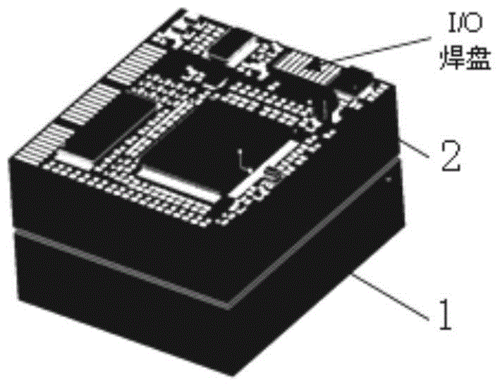
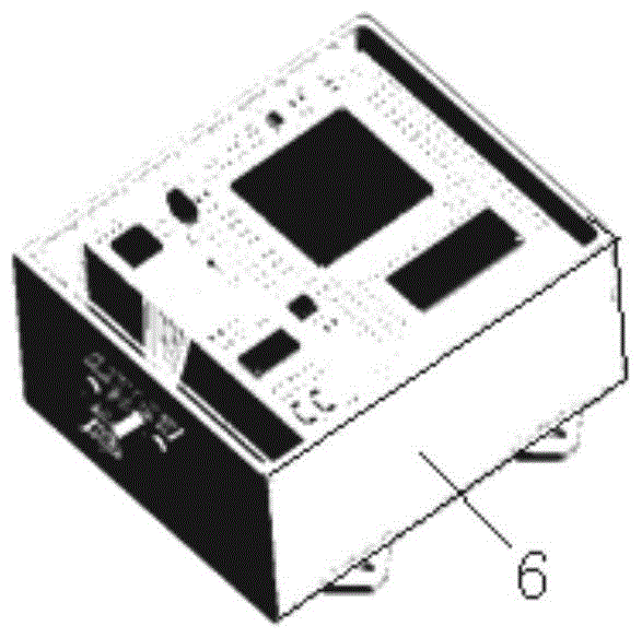
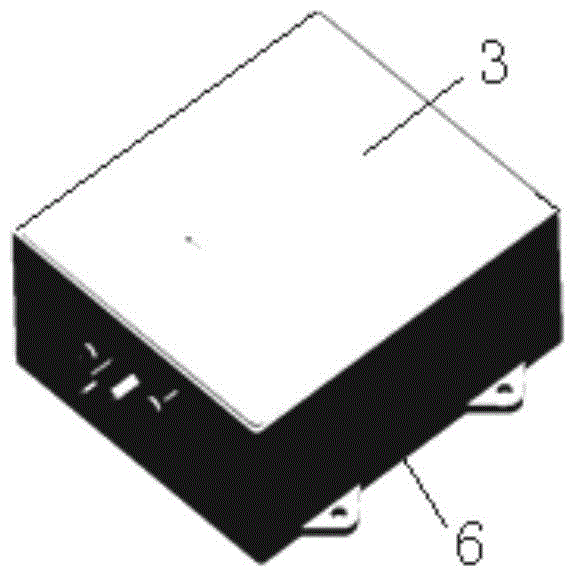
[0078] 1) combine Figure 2a , Figure 2b , using the LTCC module design, the MIMU components are divided into four modules of X-axis, Y-axis, Z-axis and main control. The circuit devices of each module are integrated on the LTCC substrate, among which the Z-axis module and the main control The module is also called "upper module 2") with a cavity on the LTCC substrate;

[0079] 2) Using SMT (Surface Mount Technology), assemble all circuit devices in micro-packages (including MEMS gyroscopes and MEMS accelerometers) onto corresponding LTCC substrates to form 4 types of LTCC circui...


PUM


Abstract

The invention discloses a low temperature co-fired ceramic (LTCC) technology micro inertial measurement unit (MIMU)-based three-axis structure and a manufacturing technology thereof. Circuit devices of X-axis, Y-axis, Z-axis and main control modules are respectively assembled to a LTCC substrate by SMT, the X-axis module and the Y-axis module are installed on a cavity base plate of the LTCC substrate of the Z-axis module in an orthogonal edge-on way so that a three-axis detection module is formed, and the main control module and the three-axis detection module are provided with BGA and are welded to form the three-axis MIMU assembly. The structure provided by the invention adopts a module design, has a small volume and light weight, and reduces size effect-caused adverse influences. Interconnection lines between devices are short so that transmission loss and crosstalk are reduced. The X-axis module and the Y-axis module are installed on a cavity base plate of the LTCC substrate of the Z-axis module in an orthogonal edge-on way so that X-Y-Z three-axis inertial 3D orthogonal detection is effectively realized. The structure is simple. The manufacturing technology has reliable processes and installation accuracy. A housing heat-radiation boss improves MIMU heat radiation performances and extraneous electromagnetic interference resistance.

Description

technical field [0001] The invention relates to a three-axis structure and manufacturing process of a micro inertial measurement unit based on LTCC technology. Background technique [0002] Micro-inertial measurement unit (MIMU) is an autonomous navigation system that does not rely on any external information and does not radiate energy outward. It can provide continuous real-time information on the position, velocity and attitude of the moving carrier. It has good concealment and is not susceptible to external interference. , high data update rate, high short-term accuracy and good stability, etc. It is mainly composed of two parts: data collection and navigation solution. [0003] The data acquisition part consists of inertial measurement element, temperature sensor, three-axis electronic compass, MEMS (micro-electromechanical system) pressure sensor, signal conditioning circuit, A / D (digital / analog) conversion circuit and FPGA (field programmable gate array) controller a...

Claims


Application Information

Patent Timeline
Patent Type & Authority Patents(China)
IPC IPC(8): G01C25/00
CPCG01C21/16G01C25/005
Inventor 何中伟俞瑛周冬莲贺彪杜松
Owner EAST CHINA INST OF OPTOELECTRONICS INTEGRATEDDEVICE
Learn More