Coupled oscillatory circuit for vehicle detection

A coupling oscillation and vehicle detection technology, which is applied in the direction of circuit devices, power oscillators, emergency protection circuit devices, etc., can solve the problems of transformer and transistor damage, oscillation circuit damage, and affecting the service life of vehicle detectors, so as to prevent damage, Effect of improving stability and service life

Inactive Publication Date: 2015-04-01
CHENGDU HEYIN TECH
View PDF3 Cites 2 Cited by
  • Summary
  • Abstract
  • Description
  • Claims
  • Application Information

AI Technical Summary

Problems solved by technology

In the vehicle detector, it is usually necessary to add a coupling oscillation circuit. In the coupling oscillation circuit, transformers, transistors, etc. are needed. However, the transformers and transistors in the coupling oscillation circuit i

Method used


Image

  • Coupled oscillatory circuit for vehicle detection

Examples


Embodiment 1

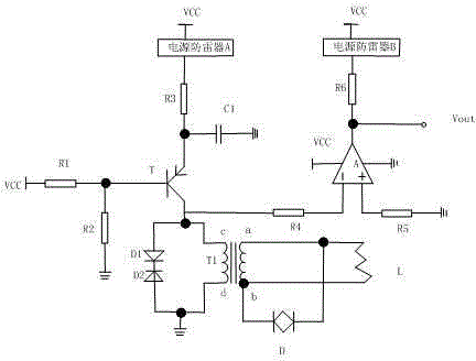
[0016] Such as figure 1 As shown, the present invention includes that the resistance R1 is 5.6 kilohms, the resistance R2 is 5.6 kilohms, the resistance R3 is 330 kilohms, the resistance R4 is 1 thousand ohms, the resistance R5 is 1 thousand ohms, the resistance R6 is 1 thousand ohms, and the triode T , coupling transformer T1, toroidal coil L, comparator A model is LM339, diode D1, diode D2, momentary suppression diode D model is P6KE12CA and two power surge protectors, between the a terminal and b terminal of the coupling transformer T1 The toroidal coil L is connected between them, the instantaneous suppression diode D is connected in parallel at both ends of the toroidal coil L, the diode D1 and the diode D2 are connected in series between the c-terminal and the d-terminal of the coupling transformer T1 and the diode D1 and the diode D2 are reversely connected, and the coupling transformer T1 The c terminal is also connected to the collector of the resistor R4 and the trio...

Embodiment 2

[0020] The preferred specific structure of this embodiment on the basis of Embodiment 1 is as follows: the ratio of the number of turns between the primary coil and the secondary coil of the coupling transformer T1 is 1:1. Since one loop ground coil corresponds to one detection channel, the inductance generated by the loop coil has the same voltage after being processed by the coupling transformer, so that the inductance of multiple detection channels can be fused into one signal for processing.

[0021] The emitter of the transistor T is connected to the pull-down capacitor C1. It is used to filter the influence of harmonics on the triode T, thereby improving the stability of the vehicle detector.

[0022] Both the diode D2 and the terminal d of the coupling transformer T1 are grounded.

[0023] The reverse breakdown voltages of the diode D1 and the diode D2 are equal to 4.3V.


PUM


Abstract

The invention discloses a coupled oscillatory circuit for vehicle detection. The coupled oscillatory circuit includes a resistor R1, resistors from R2 to R6, a coupling transformer T1, a loop coil L, a comparator A, diodes of D1 and D2, a transient voltage suppressor D and two power source lightning protectors; the loop coil L is connected between an a end and a b end of the coupling transformer T1; the transient voltage suppressor D is connected in parallel at two ends of the loop coil L; the diode D1 and the diode D2 are sequentially connected in series between a c end and a d end of the coupling transformer T1, wherein the diode D1 and the diode D2 are in reverse connection with each other; the c end of the coupling transformer T1 is also connected with the resistor R4 and the collector of a triode T simultaneously; the base of the triode T is connected with the resistor R1 and a power source VCC sequentially; and the emitter of the triode T is connected with the resistor R3, the power source lightning protectors and the power source VCC sequentially. With the above coupled oscillatory circuit adopted, damage which is caused by intrusion of lightning and other internal voltage can be avoided, and the transformer can be prevented from being damaged by transient high voltage, and therefore, the stability of a vehicle detector can be improved, and the service life of the vehicle detector can be prolonged.

Description

technical field [0001] The invention relates to the field of vehicle detection, in particular to a coupling oscillation circuit for vehicle detection. Background technique [0002] With the development of the economy, intelligent transportation has quietly emerged in our country. As an important part of traffic information collection, vehicle detectors have attracted more and more attention from the industry. The vehicle detector takes the motor vehicle as the detection target, detects the passage or existence of the vehicle, and its function is to provide sufficient information for the intelligent traffic control system to perform optimal control. At present, the commonly used vehicle detectors in the world mainly include loop coil vehicles. Detectors, video vehicle detectors and microwave vehicle detectors, among which toroidal coil vehicle detectors are widely used due to their high accuracy, low cost, and high reliability. In the vehicle detector, it is usually necessar...

Claims


Application Information

Patent Timeline
IPC IPC(8): H03B5/18H02H9/04
Inventor 龙翔
Owner CHENGDU HEYIN TECH
Why Eureka
Try Eureka