Glass composite, electronic device, and input device

A glass composite and glass technology, which is applied in branch equipment, electronic equipment, elastic/clamping devices, etc., can solve the problems of poor visual confirmation and increased cost of glass substrates, and achieve good optical properties and visual confirmation sex good effect

Inactive Publication Date: 2015-04-01
ALPS ALPINE CO LTD
View PDF6 Cites 0 Cited by
  • Summary
  • Abstract
  • Description
  • Claims
  • Application Information

AI Technical Summary

Problems solved by technology

However, in the case of processing circular holes, oval holes, etc., and three-dimensional processing of the external shape in order to match the design of electronic equipment, the cost of the glass substrate increases, which is a problem.
In addition, in the case of using a resin base material and disposing it on the screen of a display device, there is a disadvantage that the visibility is poorer than that of a glass base material.

Method used


Image

  • Glass composite, electronic device, and input device
  • Glass composite, electronic device, and input device
  • Glass composite, electronic device, and input device

Examples


no. 1 approach

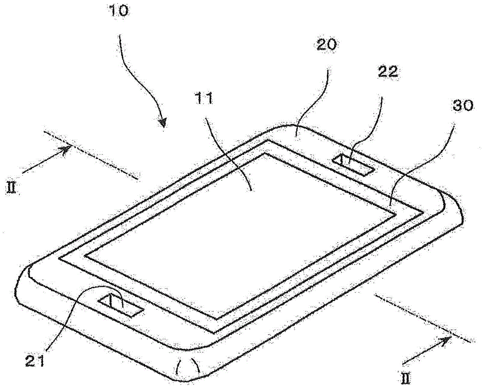
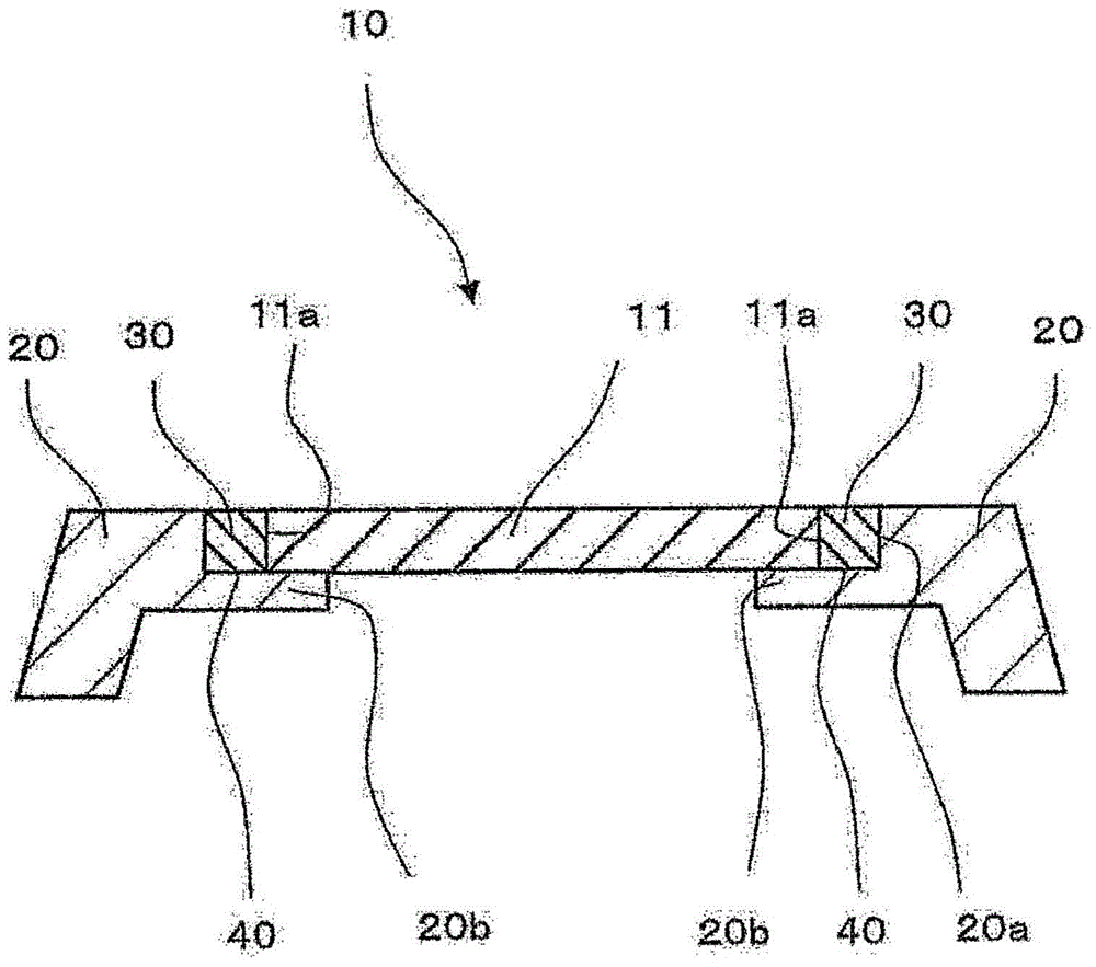
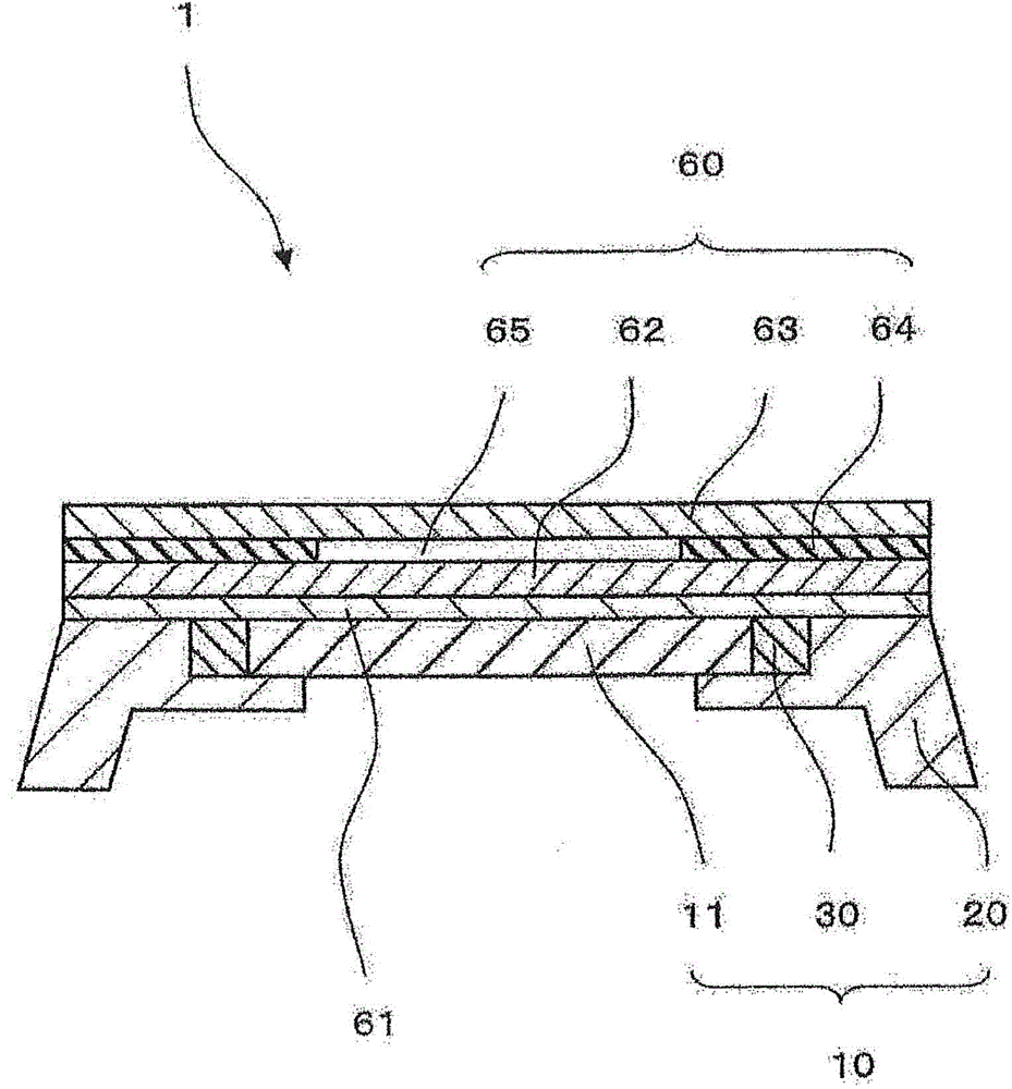
[0111] figure 1 is a perspective view showing a glass composite 10 according to the first embodiment of the present invention, figure 2 By figure 1 The schematic longitudinal sectional view obtained by cutting the II-II line, image 3 It is a schematic longitudinal cross-sectional view of the input device 1 provided with the detection panel 60 on the glass composite 10 . figure 1 and figure 2 The glass composite body 10 shown is the substrate constituting the input device 1, such as image 3 As shown, it is fixedly provided with a detection panel 60, and is used in a mobile phone, a portable game device, and the like.

[0112] Such as figure 1 As shown, in the glass composite 10 , the quadrangular region in the center is the flat glass member 11 , and the region surrounding the glass member 11 is the frame 20 . Glass member 11 is fixed to frame body 20 via adhesive member 30 . Such as figure 1 and figure 2 As shown, a filling portion 40 filling the bonding member 3...

no. 2 approach

[0134] Figure 5 It is a schematic longitudinal sectional view showing the input device 1 according to the second embodiment of the present invention. The difference from the input device 1 of the first embodiment is that a light-transmitting lower resistive film (not shown) such as ITO is formed on the glass composite 10 , and an adhesive layer is provided between the upper substrate 63 and the upper substrate 63 . In the formed spacer layer 64 , the lower resistive film and the upper resistive film (not shown) of the upper substrate 63 are opposed to each other via the gap 65 . It should be noted that the upper substrate 63 is usually formed as a structure in which the surface base material is also fixed, but in Figure 5 The illustration is omitted.

[0135] As a method of forming the translucent lower resistive film on the glass composite 10, a film may be formed directly on the glass composite 10 by vapor deposition, sputtering, or the like. When the ITO film is formed...

no. 3 approach

[0138] Figure 6 is a schematic longitudinal sectional view showing a glass composite 10 according to a third embodiment of the present invention, Figure 7 It is a schematic longitudinal cross-sectional view showing the input device 1 using the glass composite 10 of the third embodiment.

[0139] In this embodiment, if Figure 6 As shown, the side surface 11a of the glass member 11 which comprises the glass composite body 10 is grind|polished, and the shape which has the notch part 11c is formed. Here, the notch part 11c is a part of the side surface 11a, and shows the additional grinding process area. In addition, in the frame body 20, an extension portion 20c is formed on the side wall portion 20a. The extension portion 20c is a part of the side wall portion 20a of the frame body 20 . Therefore, since the extension part 20c of the frame body 20 does not protrude to the back surface of the glass member 11, the back peripheral edge part of the glass member 11 can be forme...


PUM

PropertyMeasurementUnit
thicknessaaaaaaaaaa
thicknessaaaaaaaaaa

Abstract

The invention refers to a glass composite which is ideal for quantity production and comprises a frame and glass that are integrated. A glass composite (10) of the present application is characterized by comprising a glass member (11) that transmits visible light, a frame (20) that supports the glass member (11), and an adhesive member (30) that adheres the glass member (11) to the frame (20), by the glass member (11) being a flat sheet and comprising a side surface (11a) around the periphery thereof and furthermore the side surface (11a) being fixed to the frame (20) by means of the adhesive member (30), and by the adhesive member (30) constituting a buffer layer that mitigates stress applied to the frame (20).

Description

[0001] This application is a divisional application of the international PCT application with application number 201180017338.2, international filing date of April 7, 2011, and invention title "glass composite, electronic equipment using a glass composite, and input device". technical field [0002] The present invention relates to a glass composite, an electronic device and an input device using the glass composite, and particularly relates to a structure of a glass composite capable of preventing cracks. Background technique [0003] Currently, portable electronic devices and the like are provided with an input device arranged to overlap with a display device. The main body of the input device is composed of a light-transmitting substrate, and an input operation can be performed by touching a detection area with a finger or the like while visually confirming the display content on the screen of the display device through the substrate. [0004] Such an input device is arra...

Claims


Application Information

Patent Timeline
Patent Type & Authority Applications(China)
IPC IPC(8): H05K5/02H04M1/02G06F1/16G06F3/044G06F3/045
CPCH04M1/0283H05K5/03C03C27/02B32B17/10H05K7/12B32B7/12B32B2457/20B32B2307/412B32B2307/202
Inventor 北野定雄佐藤实小池祐介桥田淳二
Owner ALPS ALPINE CO LTD
Why Eureka
Try Eureka