
The synchronous control system between the push claw device and the center box device and the automatic machine in the capsule machine

A technology of synchronous control and automaton, which is applied in the fields of capsule delivery, drug delivery, and pharmaceutical formulations. It can solve problems such as higher and higher requirements for equipment automation, connection failures of operating units, and increased maintenance workload. Improve the effect of asynchronous and impact-prone failures, reduce maintenance costs, and reduce mechanical damage

Inactive Publication Date: 2018-05-01
丹东市金丸药用胶囊机械有限公司
View PDF4 Cites 0 Cited by
  • Summary
  • Abstract
  • Description
  • Claims
  • Application Information

AI Technical Summary

Problems solved by technology

Since each operating unit is relatively independent, it is inevitable that operating unit failures will occur during the long-term production process. For example, the push claw device, the center box device and the automatic machine are three independent operating units, and control often occurs during the short-range operation of the entire system. Disharmony, collision phenomenon, or connection failure between operating units due to parameter setting problems, etc., will cause damage to the equipment, increase the workload of maintenance, and directly affect the quality of the product. With the development of production line equipment, the impact on Equipment automation requirements are getting higher and higher
[0003] At present, there is no report on the synchronous control system of the capsule machine that can meet the above requirements.

Method used


Image

  • The synchronous control system between the push claw device and the center box device and the automatic machine in the capsule machine
  • The synchronous control system between the push claw device and the center box device and the automatic machine in the capsule machine

Examples


Embodiment Construction

[0046] The present invention will be further elaborated below in conjunction with the accompanying drawings of the description.

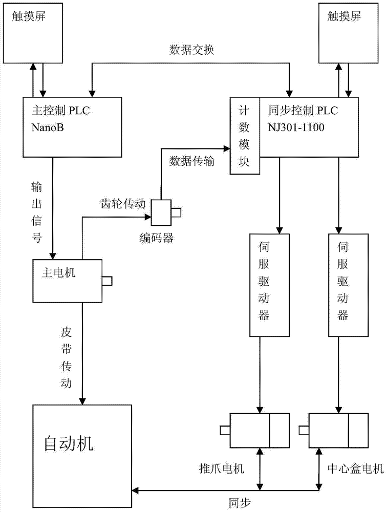
[0047] Such as figure 1 As shown, the synchronous control system between the push claw device and the center box device and the automatic machine in the capsule machine of the present invention has a main control unit and a synchronous control unit, wherein the output terminal of the main control unit is connected with a main motor control circuit, and the main motor passes through the transmission device Drive the automatic machine to run; the synchronous control unit collects the speed data of the main motor through the encoder, the synchronous control unit controls the claw motor and the center box motor respectively through two servo drivers, and the main control unit communicates with the synchronous control unit.

[0048] The main motor is connected to the reduction box, one side of the output shaft of the reduction box pulls the mechanical au...


PUM


Abstract

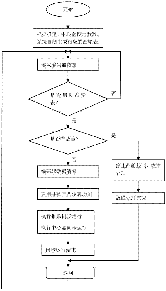
The invention relates to a synchronous control system for a push claw device, a center box device and an automatic machine in a capsule machine. The output terminal of the main control unit is connected with a main motor control circuit, and the main motor drives the automatic machine to run through a transmission device; the synchronous control unit passes a coding The speed data of the main motor is collected by the controller, the synchronous control unit controls the claw motor and the center box motor respectively through two servo drivers, and the main control unit communicates with the synchronous control unit; the method is: according to the set parameters, the synchronous control unit generates The cam table; the synchronous control unit reads the encoder data; if the automatic machine driven by the main motor is in place, the cam table is started, and the encoder data is cleared; the claw device operates synchronously, and the center box device operates synchronously; after the synchronous operation, it returns to Read encoder data step. The invention improves the asynchronous and easy-to-collision faults existing in the original production line, reduces the mechanical damage caused by the collision, ensures the normal operation of production, and reduces the maintenance cost.

Description

technical field [0001] The invention relates to a control technology of a capsule machine, specifically a synchronous control system for a push claw device, a center box device and an automatic machine in a capsule machine. Background technique [0002] At present, each movement unit of the capsule production line operates independently. Each movement unit is either input by an external signal or identified by the internal code of the PLC, and the corresponding parameters are input by personnel with certain professional skills, so that each movement unit can be effectively integrated into a production line. , to produce capsules. Since each operating unit is relatively independent, it is inevitable that operating unit failures will occur during the long-term production process. For example, the push claw device, the center box device and the automatic machine are three independent operating units, and control often occurs during the short-range operation of the entire system...

Claims


Application Information

Patent Timeline
Patent Type & Authority Patents(China)
IPC IPC(8): A61J3/07
Inventor 贾毅朱光耀何福银王平栾国利辛伟赵丹宇唐欣王镇奎庞煜磊周鹏飞
Owner 丹东市金丸药用胶囊机械有限公司
Learn More