

Cutting fluid recycling device
A recovery device and cutting fluid technology, which is applied in the direction of grinding/polishing equipment, maintenance and safety accessories, mobile filter element filters, etc., can solve the problems of mixed metal fragments, low processing accuracy, complex structure, etc., and achieve cost reduction Low cost, good recycling quality and high efficiency
- Summary
- Abstract
- Description
- Claims
- Application Information
AI Technical Summary
Problems solved by technology
Method used
Image

Examples
Embodiment Construction
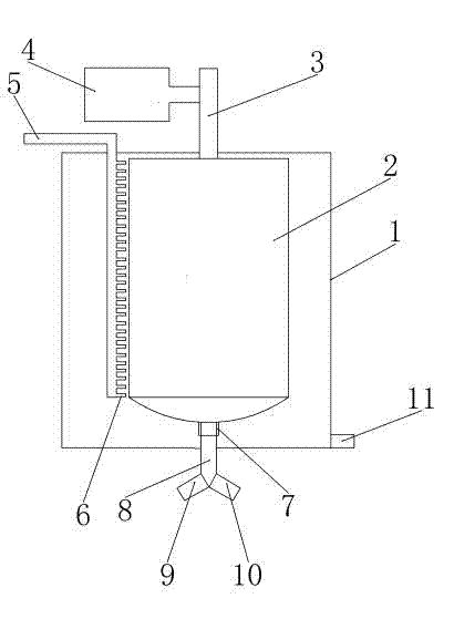
[0013] Such as figure 1 As shown, the present invention provides a cutting fluid recovery device, including a casing 1, the casing 1 is provided with a liquid outlet pipe 11 and a shock absorber, and a centrifugal roller 2 is pivotally connected to the casing 1, and the centrifugal roller 2 The side of the centrifugal roller 2 is a sieve-like dense hole, one end of the centrifugal roller 2 is connected to the rotating shaft 3, and the rotating shaft 3 is connected to the motor 4, and the funnel-shaped end of the centrifugal roller 2 is connected to the main pipe 8 through the sealing ring 7, and the main pipe 8 is connected to the feeder in a branched manner. Material pipe 9 and outlet pipe 10, housing 1 is provided with recoil water pipe 5, said recoil water pipe 5 is provided with water spray head 6 aimed at centrifugal roller 2, and water spray head 6 is along the centrifugal roller 2. A row of sprinkler heads 6 arranged radially.
[0014] The cutting fluid with metal frag...
PUM
 Abstract
Description
Claims
Application Information