
Oil product storage tank safety protection device and protection method

A safety protection device and technology for oil products, applied in packaging, transportation, packaging, containers, etc., can solve the problems of accelerating the volatilization speed of oil surface, and achieve the effect of simple protection method, elimination of hidden dangers of explosion and convenient installation.

Active Publication Date: 2015-04-08
VITALONG FIRE SAFETY GRP
View PDF6 Cites 16 Cited by
  • Summary
  • Abstract
  • Description
  • Claims
  • Application Information

AI Technical Summary

Problems solved by technology

[0002] The oil in the existing oil storage tank is evaporated due to the temperature difference between day and night, and the oil is volatilized due to the agitation of oil extraction and oil filling. The volatilization speed of the oil surface makes the oil storage tank to the inner cavity of the tank top full of a large amount of oil and gas, and there is a hidden danger of oil and gas combustion and explosion caused by lightning strikes and static electricity

Method used


Image

  • Oil product storage tank safety protection device and protection method
  • Oil product storage tank safety protection device and protection method
  • Oil product storage tank safety protection device and protection method

Examples


Embodiment 1

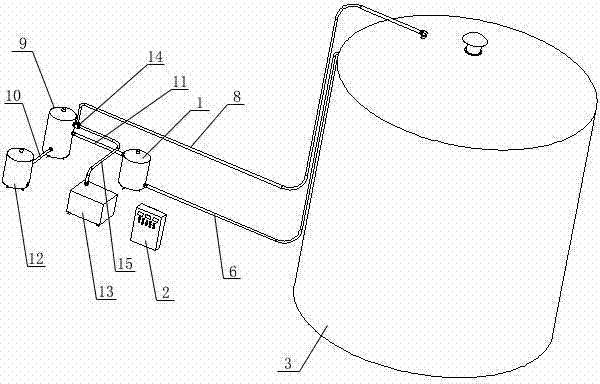
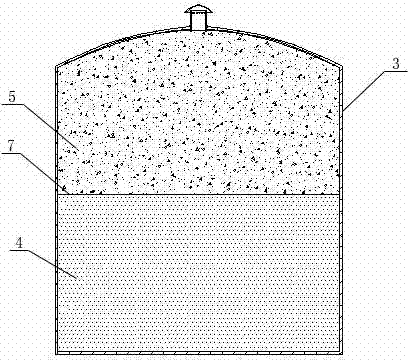
[0028] Embodiment 1: as figure 1 , figure 2 , Figure 5 As shown, an oil storage tank safety protection device includes a gas analysis unit, an inhibitor supply unit 1, and a control unit 2. The gas analysis unit includes an air extraction sampling analysis system 13, and the air extraction sampling analysis system 13 passes The main air extraction pipe 8 is connected to the mixed gas space 5 formed above the liquid level of the oil product 4 in the oil storage tank 3, the inhibitor supply unit 1 is connected to the oil storage tank 3 through the inhibitor supply pipe 6, and the control unit 2 is respectively It is connected with the air pumping sampling analysis system 13 and the inhibitor supply unit 1, and the inhibitor injected into the oil storage tank 3 by the inhibitor supply unit 1 through the inhibitor supply pipe 6 forms a liquid film protective layer on the liquid surface of the oil product 4 7.

[0029]Wherein, the mixed gas space 5 in the oil storage tank 3 is...

Embodiment 2

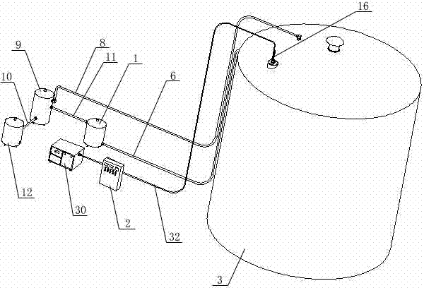
[0034] Embodiment 2: as Figure 3 ~ Figure 4 , Figure 6 ~ Figure 10 As shown, the gas analysis unit includes a bidirectional self-cleaning fiber optic gas sensor sensing head 16 arranged on the oil storage tank 3, and the bidirectional self-cleaning fiber optic gas sensor sensing head 16 includes a fiber optic signal transceiver unit, a fiber optic signal Reflection unit and bi-directional purge unit.

[0035] Wherein, the optical fiber signal transceiver unit includes an optical fiber group 17 and a two-way light-transmitting mirror 18, the optical fiber group 17 is connected to the control unit 2 through a laser transmitter, a sheath 20 is placed on the optical fiber group 17, and the sheath 20 The coated optical fiber group 17 is connected to the inner hole of the positioning sleeve 21, and the positioning sleeve 21 is fixedly connected with the end surface of the main body 22 after being positioned, and the positioning sleeve and the main body are fastened by threads; th...


PUM


Abstract

The invention discloses an oil product storage tank safety protection device and protection method. The oil product storage tank safety protection device comprises a gas analyzing unit, an inhibitor supply unit and a control unit, the gas analyzing unit is connected with a mixed gas space formed above the liquid surface of oil product in the oil storage tank, the inhibitor supply unit is connected with the oil storage tank through an inhibitor supply pipe, and the control unit is respectively connected with the gas analyzing unit and inhibitor supply unit. The oil product storage tank safety protection device and protection method are mainly used for flammable and combustible spaces formed by oil evaporation in crude oil storage tanks and product oil tanks, the gas analyzing unit detects the concentration of the mixed gas in the space above the liquid surface of the oil product in the oil storage tank, the inhibitor supply unit fills inhibitor to the surface of the oil product in the oil storage tank, and the filled inhibitor can form a liquid film protection layer at the surface of the oil product and reduce the oil gas evaporation and volatilization of the oil product; the oil gas concentration is reduced through the evaporation of the liquid film, and accordingly the inactive protection for the oil gas space is realized.

Description

technical field [0001] The invention belongs to the field of fire safety in the petroleum and petrochemical industry, and in particular relates to a safety protection device for an oil storage tank and a protection method thereof. Background technique [0002] The oil in the existing oil storage tank is evaporated due to the temperature difference between day and night, and the oil is volatilized due to the agitation of oil extraction and oil filling. The volatilization speed of the oil surface makes the oil storage tank to the inner cavity of the tank top full of a large amount of oil gas, and there is a hidden danger of oil gas combustion and explosion caused by lightning strikes and static electricity. Contents of the invention [0003] The purpose of the present invention is to solve the above-mentioned problems and provide a safety protection device for oil storage tanks that can effectively inhibit the evaporation of the oil surface, and can also recover and process ...

Claims


Application Information

Patent Timeline
Patent Type & Authority Applications(China)
IPC IPC(8): B65D90/22
CPCB65D90/42B65D90/48
Inventor 汪映标张宗勤张宁甲胡安林
Owner VITALONG FIRE SAFETY GRP
Learn More