

Thyristor single-phase voltage adjusting circuit and control method thereof
A voltage regulation circuit and thyristor technology, which is applied in the control field to ensure stable triggering, cost reduction and small fluctuation range.
- Summary
- Abstract
- Description
- Claims
- Application Information
AI Technical Summary
Problems solved by technology
Method used
Image

Examples
Embodiment 1
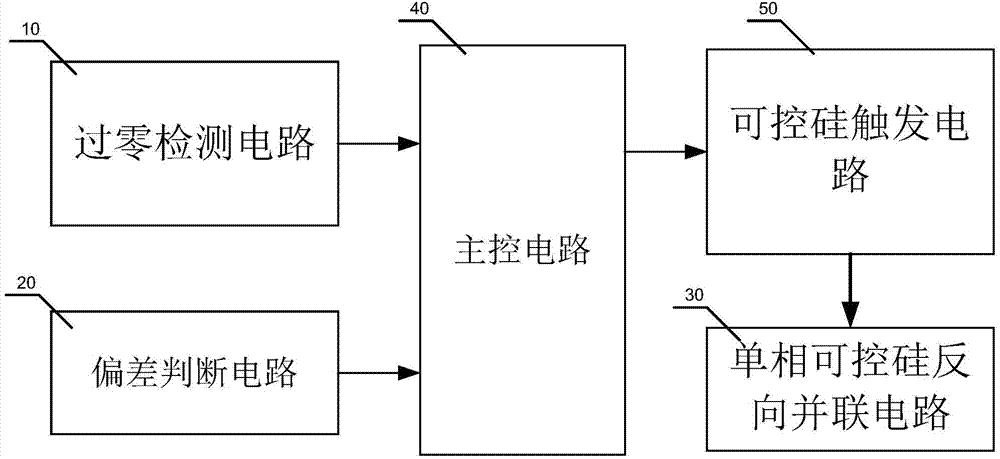
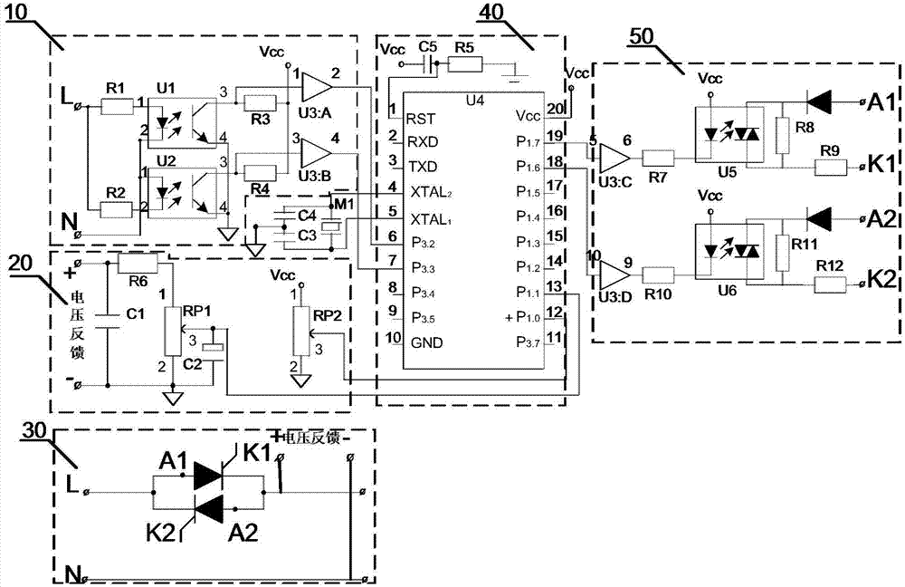
[0021] Embodiment 1: refer to figure 1 and figure 2 , a thyristor single-phase voltage regulating circuit of the present invention, comprising a main control circuit 40 electrically connected to a zero-crossing detection circuit 10, a thyristor trigger circuit 50 and a deviation judgment circuit 20, and the thyristor trigger circuit 50 is connected to a single It is electrically connected to the thyristor antiparallel circuit 30 . L in the zero-crossing detection circuit 10 is connected to the live wire of the power supply, and N is connected to the neutral wire of the power supply. When the positive half-wave of the power supply enters, the voltage of the L terminal is higher than the voltage of the N terminal, and the current flows from the L terminal through the resistor R1, then flows into the 2 pin of the photocoupler U1, and finally flows into the N terminal, thus , the light-emitting diode inside the optocoupler U1 emits light. When the light-emitting diode of photo...
Embodiment 2
[0029] Embodiment 2: refer to Figure 4 , a thyristor single-phase voltage regulating circuit voltage regulating circuit of embodiment 2 is basically the same as that of embodiment 1, the difference is: a thyristor 30 is installed between the fire line L and the deviation judgment circuit 20 A current detection circuit 60 is set, and a current transformer 601 collects an AC current signal on the live line L, and the obtained AC current signal is converted into a DC current signal through a rectifier bridge 602 . The DC current signal becomes a negative voltage signal through the resistor R1, and is filtered by the capacitor C and sent to the inverting amplifier composed of LM358, R1 and R2 for inverting amplification, and then connected to the deviation judgment circuit 20 through + and - of the voltage feedback + and - on for voltage feedback.
PUM
 Abstract
Description
Claims
Application Information