Supercharge Your Innovation With Domain-Expert AI Agents!

Chamber structure applied to plasma equipment and plasma equipment

A plasma and chamber technology, applied in the field of plasma, which can solve the problems of process performance, such as etching speed and etching uniformity, which cannot be precisely controlled.

Active Publication Date: 2015-04-08
中国科学院嘉兴微电子仪器与设备工程中心
View PDF6 Cites 1 Cited by
  • Summary
  • Abstract
  • Description
  • Claims
  • Application Information

AI Technical Summary

Problems solved by technology

[0004] However, in the chamber structure of the existing plasma equipment, the product is arranged on the substrate 13, and there is a vacuum between the substrate 13 and the plasma 15, so that when the plasma 15 reacts with the surface of the product, the plasma 15 The density is constant, resulting in the inability to accurately control the corresponding local process performance capabilities such as etching speed and etching uniformity

Method used


Image

  • Chamber structure applied to plasma equipment and plasma equipment
  • Chamber structure applied to plasma equipment and plasma equipment
  • Chamber structure applied to plasma equipment and plasma equipment

Examples


Embodiment Construction

[0021] The embodiment of the present application provides a chamber structure and plasma equipment applied to plasma equipment, which can increase the density of plasma, thereby adjusting the corresponding local process performance capabilities such as etching speed, etching uniformity, etc. , to improve product quality.

[0022] The main realization principles, specific implementation modes and corresponding beneficial effects of the technical solutions of the embodiments of the present invention will be described in detail below in conjunction with each accompanying drawing.

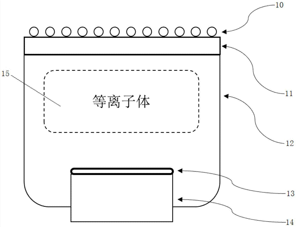
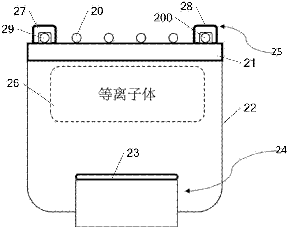
[0023] An embodiment of the present invention proposes a chamber structure applied to plasma equipment, see figure 2 , including a radio frequency coil 20, a quartz coupling window 21, a cavity 22, a substrate 23, a lower electrode 24 and a magnetizer 25, the radio frequency coil 20 is arranged on the upper part of the quartz coupling window 21, and the quartz coupling window 21 is arranged on the upp...


PUM


Abstract

The invention discloses a chamber structure applied to plasma equipment and the plasma equipment. The chamber structure comprises a radio frequency coil, a quartz coupling window, a chamber, a substrate and a lower electrode, wherein the radio frequency coil is arranged on the upper part of the quartz coupling window; the quartz coupling window is arranged on the upper part of the chamber; the substrate is arranged on the upper part of the lower electrode; the substrate and the lower electrode are arranged on the lower part of the chamber; a plasma focusing structure is arranged in the chamber and is arranged on the lower part of plasma arranged in the chamber for controlling fluid distribution of the plasma; the magnetic member is connected with the plasma focusing structure for applying a magnetic field. According to the embodiment of the invention, by providing the chamber structure applied to the plasma equipment and the plasma equipment, the fluid distribution of the plasma can be controlled, so the surface reaction of the plasma and a product is fuller, and the qualification rate and the yield of the product are improved.

Description

technical field [0001] The invention relates to the field of plasma technology, in particular to a chamber structure applied to plasma equipment and the plasma equipment. Background technique [0002] With the rapid development of plasma technology, large-area and high-density plasma sources, such as ECR, ICP and TCP plasma, are used in the manufacture of large-scale integrated circuits. The manufacturing process will be affected by plasma density, electron temperature, and gas flow. And the impact of parameters such as reaction temperature, and then by controlling the hardware parameters and process parameters of the plasma equipment, the product can be processed with better process conditions, so that the pass rate and yield of the product are higher. [0003] When the existing plasma equipment is processing the product, the product is usually placed in the chamber structure of the plasma equipment for plasma reaction, while the existing chamber structure such as figure 1...

Claims


Application Information

Patent Timeline
IPC IPC(8): H01J37/32H01L21/00H01L21/3065
CPCH01J37/32431H01J37/32807H01J37/32908
Inventor 张庆钊
Owner 中国科学院嘉兴微电子仪器与设备工程中心
Features
  • R&D
  • Intellectual Property
  • Life Sciences
  • Materials
  • Tech Scout
  • Unparalleled Data Quality
  • Higher Quality Content
  • 60% Fewer Hallucinations
Learn More