An RFID indoor positioning system and method using a cellular-like layout

An indoor positioning and RFID tag technology, applied in the field of RFID indoor positioning system, can solve the problems of inaccurate positioning, high difficulty of on-site deployment, and large resource requirements, so as to improve the accuracy of positioning and reduce the overlapping area of ​​space. , the effect of expanding the scope of application

Active Publication Date: 2018-05-04
FUJIAN XINO COMM TECH
View PDF6 Cites 0 Cited by
  • Summary
  • Abstract
  • Description
  • Claims
  • Application Information

AI Technical Summary

Problems solved by technology

[0003] The existing radio frequency positioning methods generally adopt the layout of RFID readers in a rectangular manner, and place reference RFID tags as coordinate positioning. For example, Chinese patent (application number 200810198382.8) discloses a radio frequency positioning method using an area positioning algorithm. Methods By comparing the signal strength of the RFID tag to be tested obtained by the reference RFID tag and the RFID reader, the location of the RFID tag to be tested is initially determined, and then the specific location of the RFID tag to be tested is further determined by using the area division algorithm. This wireless radio frequency indoor positioning system To a certain extent, the position of the RFID tag to be tested is accurate, but without anti-interference processing, the positioning accuracy is still not accurate enough, and the positioning range is small
[0004] Chinese invention patent (Application No. 200780016788.3) discloses a wireless picocellular RFID system and method, which locates through the cell to which the RFID tag belongs, and the positioning accuracy can only be determined in which cell the RFID tag is located, and the invention uses a -Optical (E-O) access point equipment requires relatively large resources to a certain extent and is difficult to deploy on site

Method used


Image

  • An RFID indoor positioning system and method using a cellular-like layout
  • An RFID indoor positioning system and method using a cellular-like layout
  • An RFID indoor positioning system and method using a cellular-like layout

Examples


Embodiment Construction

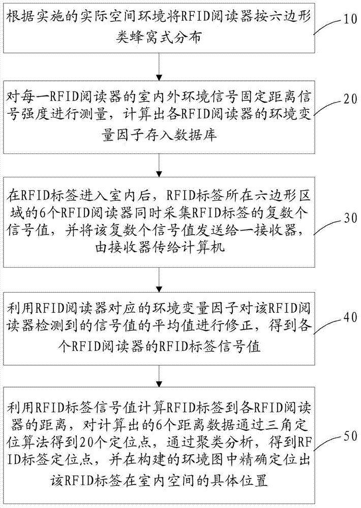
[0044] see figure 1 , a kind of RFID indoor positioning method that adopts similar honeycomb layout, improves the precision of indoor positioning by introducing environmental variable factor and combining positioning analysis algorithm, described method comprises the following steps:

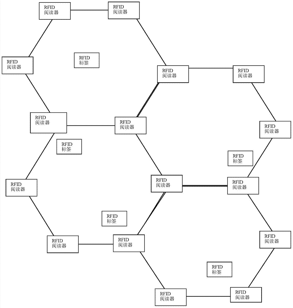
[0045] Step 10, distribute the RFID readers according to the hexagonal cellular type according to the actual space environment implemented, such as image 3 As shown, if the actual space environment implemented is a single high-rise building, the vertical distribution is adopted, and if the implemented space environment is a single-story building, the horizontal distribution is adopted, since the reading range of the RFID reader is centered on the RFID card reader , the spherical space with the radius of the RFID card reader's card reading distance makes the horizontal distribution of RFID readers according to the hexagonal honeycomb type can meet the spatial distribution needs of a single floor...


PUM


Abstract

The invention provides an RFID (radio frequency identification device) indoor positioning method adopting honeycomb type layout. The RFID indoor positioning method includes steps of distributing RFID readers in a hexagonal honeycomb manner according to a practical spatial environment of operation; calculating environmental variable factors of the RFID readers; acquiring a plurality of signal values of RFID labels by six RFID readers in the hexagonal area where the RFID labels are located; correcting the average value of the signal values of each RFID reader by means of the environmental variable factors to obtain RFID label signal values; calculating the distance between the RFID labels and the RFID readers, acquiring 20 positioning points of the calculated six distances through a like-triangle positioning algorithm, generating RFID label positioning points through cluster analysis and accordingly determining specific positions of the RFID labels in the indoor space. The invention further provides an RFID indoor positioning system adopting the honeycomb type layout, and high-precision and wide-range indoor positioning technology is realized.

Description

technical field [0001] The invention relates to the technical field of radio frequency indoor positioning, in particular to an RFID indoor positioning system and method using a cellular-like layout. Background technique [0002] Indoor positioning refers to the realization of position positioning in the indoor environment. It mainly adopts wireless communication, base station positioning, inertial navigation positioning and other technologies to form a set of indoor position positioning system, so as to realize the position monitoring of people and objects in the indoor space. Indoor positioning systems are different from outdoor positioning systems such as GPS and AGPS. At present, there is still no powerful organization to formulate uniform technical specifications. The current technical means are all developed under the private protocols and solutions defined by each enterprise. RFID (wireless Radio frequency identification technology) is one of the more commonly used pos...

Claims


Application Information

Patent Timeline
Patent Type & Authority Patents(China)
IPC IPC(8): H04W64/00G06K7/00
CPCG06K7/00G06K7/0095G06K7/10009G06K7/10099H04W64/00
Inventor 黄添福彭慧娟
Owner FUJIAN XINO COMM TECH
Why Eureka
Try Eureka