Vertical numerically controlled chamfering machine

A chamfering machine and vertical technology, applied in metal processing machinery parts, clamping, supporting and other directions, can solve the problems of large machine tool area, inconvenient replacement of tools and workpieces, etc., to reduce the area and structure. The effect of compact, simplified structure

Active Publication Date: 2015-04-15
CHONGQING MACHINE TOOL GROUP
View PDF7 Cites 6 Cited by
  • Summary
  • Abstract
  • Description
  • Claims
  • Application Information

AI Technical Summary

Problems solved by technology

The chamfering machines currently in use are basically designed for stand-alone production. If they are to be used in an automatic processing production line, the machine tool needs to be changed, and there are also defects that the machine tool occupies a large area and it is inconvenient to replace tools and workpieces.

Method used


Image

  • Vertical numerically controlled chamfering machine
  • Vertical numerically controlled chamfering machine
  • Vertical numerically controlled chamfering machine

Examples


Embodiment Construction

[0032] The present invention will be further described below in conjunction with the accompanying drawings and specific embodiments, so that those skilled in the art can better understand the present invention and implement it, but the examples given are not intended to limit the present invention.

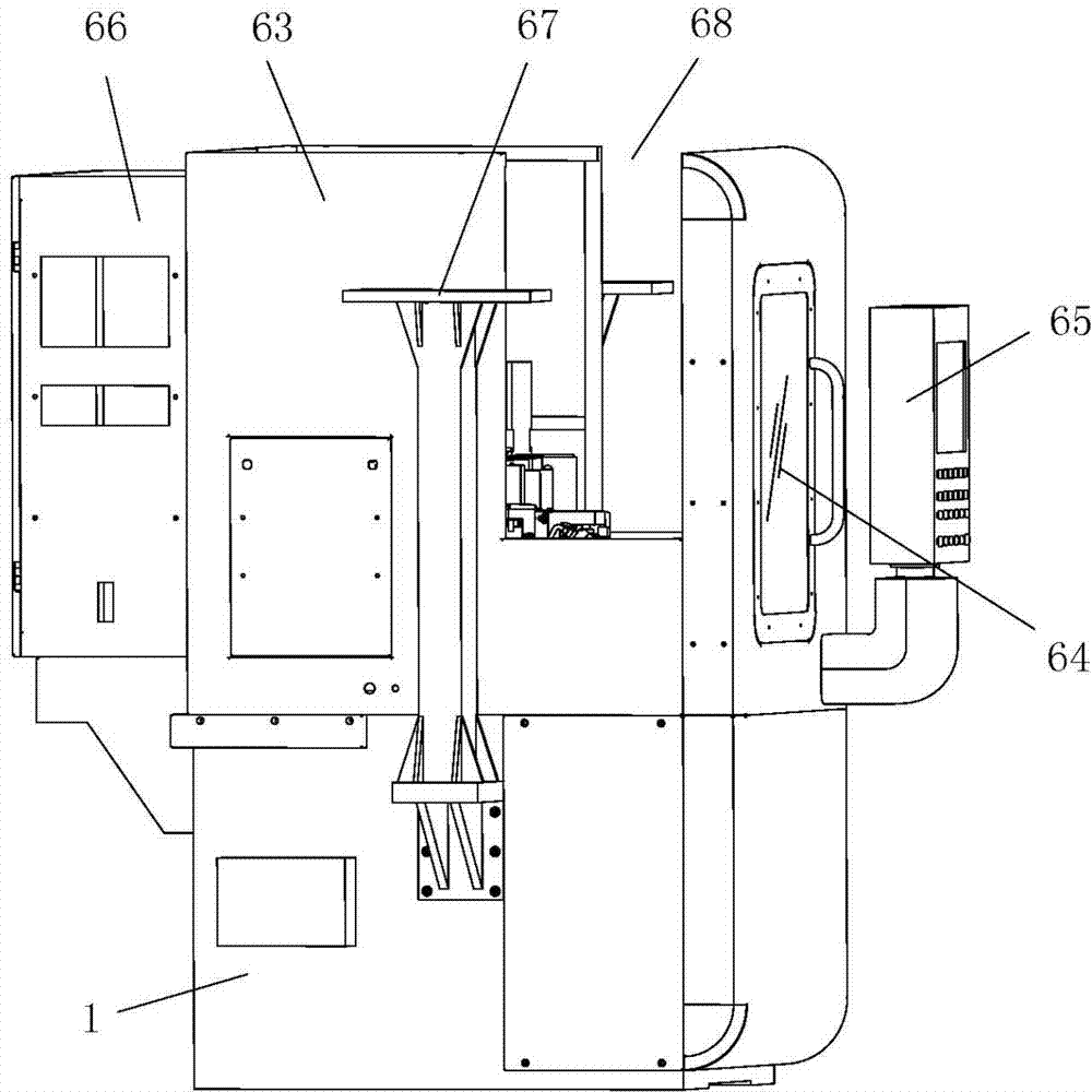
[0033] like figure 1 Shown is a schematic structural view of an embodiment of the vertical numerically controlled chamfering machine of the present invention. The vertical numerical control chamfering machine of this embodiment includes a bed 1 on which a column 2 and a workbench 3 are provided, and a chamfering mechanism and a deburring mechanism are provided in the column 2 corresponding to the workbench 3 . There is an open space above the workbench, and the manipulator on the automatic line can directly pick up and place workpieces on the workbench.

[0034] like figure 2 As shown, the workbench 3 of this embodiment includes a main shaft 4, a work platform 5 installed on th...


PUM


Abstract

The invention discloses a vertical numerically controlled chamfering machine. The machine comprises a body, and a column and a work bench are arranged on the body. A chamfering mechanism and a de-burring mechanism are arranged in the column corresponding to the work bench. Open space is formed above the work bench, and manipulators on an automatic line can take and put work-pieces on the work bench directly. The work bench comprises a spindle, a work platform and a work bench casing. An oil cavity is formed in the upper end of the spindle, a collection disc covers the oil cavity in a seal mode, a piston in sliding fit with the oil cavity is arranged in the oil cavity and divides the oil cavity into an upper oil cavity body and a lower oil cavity body, a through hole is formed in the collection disc, and an extension section extending upwards to penetrate the through hole is formed in the piston. An oil distribution ring fixedly connected with the work bench casing is sleeved on the spindle, two circular oil grooves are formed in the inner wall of the oil distribution ring, two oil channels communicated with the two circular oil grooves respectively are formed in the spindle, and the two oil channels are communicated with the upper oil cavity body and the lower oil cavity body respectively. A connection hole for being connected with a spindle drive motor is formed in the lower end of the spindle.

Description

technical field [0001] The invention belongs to the technical field of chamfering machines, in particular to a vertical numerical control chamfering machine. Background technique [0002] In the current automobile manufacturing industry, on the one hand, in order to reduce the vibration and noise of the gear box, as well as the damage to the tooth surface during the gear handling process, it is generally required to chamfer the gear tooth profile; on the other hand, the processing of the gear In the direction of automation, especially the gear automatic processing production line is more and more widely used. The automatic processing production line is processed by multiple machine tools in line, and has high requirements for the reliability, floor space, convenience of manipulator clamping workpieces, tool replacement and workpiece replacement of each machine tool. The chamfering machines currently in use are basically designed for stand-alone production. If they are to be...

Claims


Application Information

Patent Timeline
Patent Type & Authority Applications(China)
IPC IPC(8): B23P23/02B23Q3/08B23Q3/157B23Q5/40B23Q11/08
CPCB23P23/02B23Q3/082B23Q3/157B23Q5/402B23Q11/08
Inventor 李先广谢小卿廖承渝付常宝张剑波陈寅峰李明玉
Owner CHONGQING MACHINE TOOL GROUP
Why Eureka
Try Eureka