Novel throttle valve

A throttle valve and a new type of technology, applied in the field of throttle valve, can solve the problems of slow pressure adjustment process, reduced throttle valve response speed, fluid leakage, etc., to increase the service life, increase the flow area, and reduce the back pressure. Effect

Inactive Publication Date: 2015-04-15
CHINA PETROCHEMICAL CORP +1
View PDF6 Cites 11 Cited by
  • Summary
  • Abstract
  • Description
  • Claims
  • Application Information

AI Technical Summary

Problems solved by technology

The following problems mainly exist in the process of field use: the needle throttle valve and the cylindrical throttle valve are a cantilever beam structure during the throttling process, and vibration fatigue is prone to occur during the high-pressure fluid erosion process, resulting in valve stem fracture or valve failure. The core falls off, which poses a great safety hazard; the orifice throttle valve bears a large force and is severely eroded, and due to the limitations of its structural design, its flow area is always less than or equal to half of the through hole area of ​​the valve seat ;The linear working area of ​​the cylindrical throttle valve is narrow, the pressure adjustment process is slow, and in the process of drilling under pressure, when the control pressure is high, the valve position is relatively small, the ability to pass through cuttings is poor, and it is not easy to control accurately; wedge-shaped throttle The back pressure of the valve is large under the condition of large displacement, which reduces the scope of use of the wedge throttle valve in the field of precise pressure control; the hydraulic oil in the hydraulic cylinder in the form of linear hydraulic cylinder drive will delay the start and stop of the valve core. When the throttle valve is slowed down, the response speed of the throttle valve is reduced, and the constant change of the size and direction of the oil pressure causes the hydraulic cylinder seal of the throttle valve to be damaged in advance, resulting in environmental pollution problems such as hydraulic oil running, popping, dripping, and leaking, and when the hydraulic system In case of failure, the throttle valve cannot be operated manually
Existing throttle valves in China can only realize the throttling function but cannot cut off the flow. If it is used in the fine pressure control process, when it is used to cut off the flow, there will still be fluid leaking from the throttle valve, causing other Branch throttling characteristics change

Method used


Image

  • Novel throttle valve
  • Novel throttle valve
  • Novel throttle valve

Examples


Embodiment 1

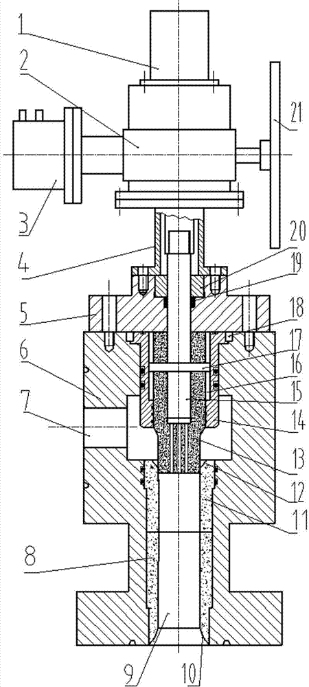
[0028] Refer to attached Figure 1 to Figure 6 , a new throttle valve includes a driver 2 , a valve cover 5 , a valve stem 15 , a valve body 6 , a valve core 13 , a valve seat 11 and a valve body bushing 8 . The driver 2 is an elevator composed of a worm gear pair and a screw pair. One end of the worm of the driver 2 is connected to the hydraulic motor 3, and the other end is installed with a handwheel 21. The upper end of the driver 2 is installed with a displacement sensor 1. The lower end of the driver 2 is connected to the support cylinder 4, which 4 The lower end is connected to the valve cover 5, the valve cover 5 is connected to the upper end of the valve body 6, the lower end of the screw rod of the driver 2 is connected to the valve stem 15, and the valve stem 15 and the valve core 13 are connected together through the connecting pin 17; the upper part of the valve body 6 is processed The anti-rotation barrel 14 is inserted into the hole, and the anti-rotation pin 18 ...

Embodiment 2

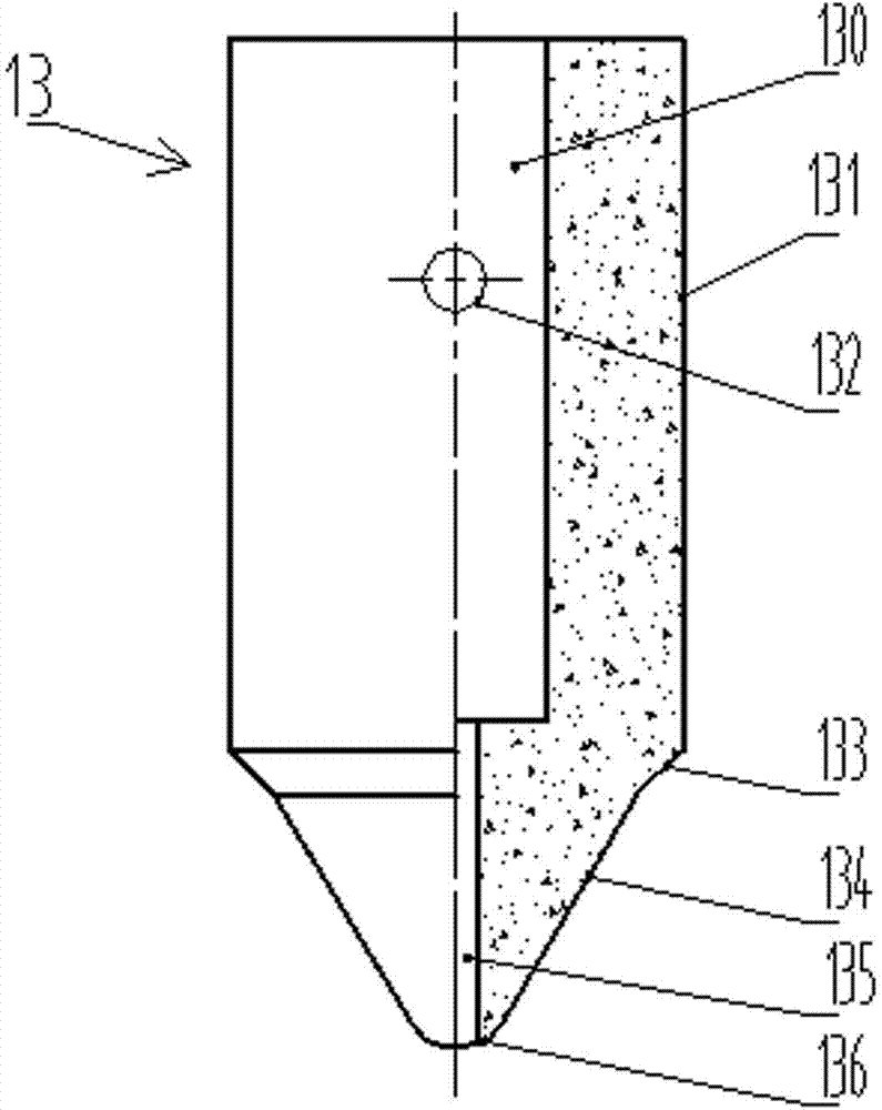
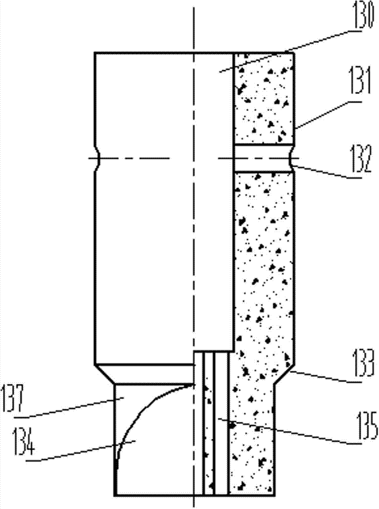
[0034]A new type of throttle valve, including a driver 2, a valve cover 5, a valve stem 15, a valve body 6, a valve core 13 and a valve seat 11, wherein: the lower part of the driver 2 is connected to the valve cover 5, and the connection between the valve cover 5 and the valve body 6 The upper end surface is connected, the lower end of the screw rod of the driver 2 is connected to the valve stem 15, and the lower part of the valve stem 15 is connected to the valve core 13; The valve core 13 is inserted into the anti-rotation cylinder 14, and forms a circumferential locking and axial sealing sliding fit with the anti-rotation cylinder 14; the side and lower part of the valve body 6 are respectively processed with inlet channels 7 and The outlet channel 9 and the valve seat 11 are installed in the outlet channel 9, and form an axial insertion fit with the upper valve core 13); the upper part of the valve core 13 is a cylinder, and the lower end is symmetrically processed with tw...

Embodiment 3

[0036] On the basis of above-mentioned embodiment 2, also include:

[0037] The driver 2 is an elevator composed of a worm gear pair and a screw pair. One end of the worm of the driver 2 is connected to the drive motor 3, and the other end is installed with a handwheel 21. A displacement sensor 1 is installed on the top of the driver 2; the lower part of the driver 2 passes through the support tube 4. Connect the bonnet 5; the anti-rotation cylinder 14 and the valve body 6 are circumferentially locked by the anti-rotation pin 18; the valve stem 15 and the valve core 13 are connected by a connecting pin 17; the valve core 13 and the anti-rotation The rotating cylinders 14 form a circumferential locking with the inner groove 16 provided on the anti-rotating cylinder 14 through the connecting pins 17 . The driving motor 3 adopts a piston-type hydraulic cylinder structure


PUM


Abstract

The invention discloses a novel throttle valve. The novel throttle valve comprises a driver, a valve cover, a valve rod, a valve body, a valve core and a valve base, wherein the lower part of the driver is connected with the valve cover; the valve cover is connected with the upper end surface of the valve body; the lower end of a lead screw of the driver is connected with the valve rod; the lower part of the valve rod is connected with the valve core; an axial hole way is formed in the upper part of the valve body; an anti-rotating cylinder is inserted in the hole way, and is peripherally locked with the valve body; the valve core is inserted in the anti-rotating cylinder, is peripherally locked with the anti-rotating cylinder, and axially fits the anti-rotating cylinder in a sealing slide manner; an inlet hole way and an outlet hole way are respectively formed in the side surface and the lower part of the valve body in the axial direction; the valve base is mounted in the outlet hole way, and axially fits the valve core at the upper side in an inserting manner; the upper part of the valve core is cylindrical; and two throttle inclined surfaces are symmetrically arranged at the lower end of the valve core, and take the shape of V. The throttle valve has the advantages of strong washout resistance, flow capacity and blockage resistance, quick valve position switch, small driver operation force, total cutoff in the closing of the valve core and adaptability to precise pressure control.

Description

technical field [0001] The invention relates to the field of throttling valves for pressure and flow control by means of throttling devices, and is particularly suitable for throttling devices for precise control of pressure in oil and gas wells. Background technique [0002] In the fields of underbalanced drilling, managed pressure drilling and other fine pressure control fields of oil and gas wells, it is necessary for the throttle valve to always control the fluid returning from the wellhead, and to control the back pressure value within a reasonable range. The throttle valve works continuously under pressure. Higher requirements are put forward for the operating reliability, service life, on-site maintainability, prevention of cuttings clogging and pressure control accuracy of the throttle valve. [0003] At present, the throttle valves used in the pressure control of oil and gas wells are mainly needle throttle valves, orifice throttle valves, cylindrical throttle valve...

Claims


Application Information

Patent Timeline
Patent Type & Authority Applications(China)
IPC IPC(8): F16K1/00F16K1/36F16K1/42F16K31/143F16K31/05F16K31/53
CPCF16K1/02F16K1/36F16K1/42F16K31/055F16K31/143F16K31/535
Inventor 朱焕刚杨德京李建成陈永明燕修良王树江
Owner CHINA PETROCHEMICAL CORP
Why Eureka
Try Eureka