Negative Charge Pump Feedback Circuit

A technology of feedback circuit and charge pump, which is applied in the direction of electrical components, conversion equipment without intermediate conversion to AC, output power conversion device, etc., can solve the problems of poor waveform, slow feedback speed, and large area occupation. To achieve the effect of reducing the circuit area

Active Publication Date: 2017-03-29
SHANGHAI HUAHONG GRACE SEMICON MFG CORP
View PDF4 Cites 0 Cited by
  • Summary
  • Abstract
  • Description
  • Claims
  • Application Information

AI Technical Summary

Problems solved by technology

[0003] Depend on figure 1 It can be seen that the resistance voltage divider circuit 104 in the existing feedback circuit is composed of multiple resistors connected in series, which will occupy a large area; and the divided voltage output by the resistance voltage divider circuit 104 is a negative value, which needs to be converted by the positive and negative voltage conversion circuit 105 Converting the divided voltage to positive pressure, the feedback speed is slow, and the waveform of the output negative voltage Vneg of the negative pressure charge pump 101 is not very good

Method used


Image

  • Negative Charge Pump Feedback Circuit
  • Negative Charge Pump Feedback Circuit
  • Negative Charge Pump Feedback Circuit

Examples


Embodiment Construction

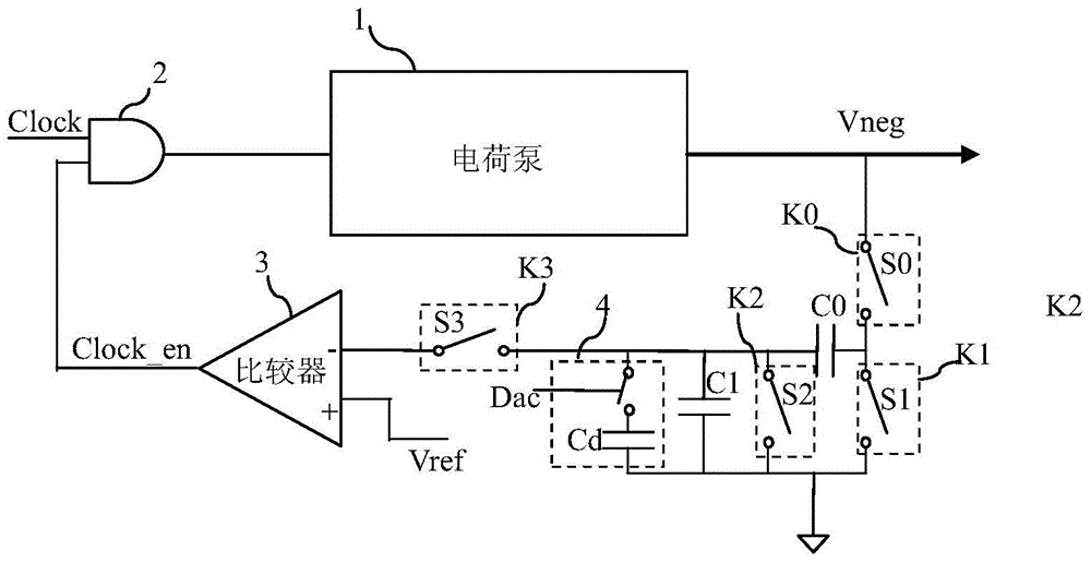
[0023] Such as figure 2 As shown, it is a schematic diagram of the feedback circuit of the negative pressure charge pump 1 of the embodiment of the present invention; in the feedback circuit of the negative pressure charge pump 1 of the embodiment of the present invention, the clock signal Clock is connected to the first input terminal of an AND gate 2, and the AND gate The output terminal of 2 is connected to the input terminal of the negative pressure charge pump 1, the output terminal of the negative pressure charge pump 1 outputs a negative voltage Vneg, and the feedback circuit is connected between the output terminal of the negative pressure charge pump 1 and the AND gate 2 The feedback circuit includes a switched capacitor circuit and a comparator 3 between the second input terminals.

[0024] The switched capacitor circuit includes:

[0025] The first capacitor C0, the first end of the first capacitor C0 is connected to the output end of the negative pressure charge ...


PUM


Abstract

The invention discloses a negative pressure charge pump feedback circuit, the feedback circuit is connected between the output end of the negative pressure charge pump and the AND gate, the clock signal is connected to the negative pressure charge pump under the control of the feedback signal through the AND gate, and the feedback The circuit includes a switched capacitor circuit and a comparator; the first end of the first capacitor of the switched capacitor circuit is connected to the output end of the negative pressure charge pump through the first switch, and grounded through the second switch; the first end of the second capacitor is connected to the first capacitor The second end of the second end is grounded through the third switch and connected to the comparator through the fourth switch; the adjustable capacitor is connected in parallel with both ends of the second capacitor; the non-inverting input end of the comparator is connected with a reference voltage. The control of the four switches by the four control signals makes the switched capacitor circuit continuously switch between the two states, realizing voltage division and positive and negative voltage conversion. The invention can reduce the circuit area, accelerate the feedback speed and reduce the output voltage ripple of the charge pump.

Description

technical field [0001] The invention relates to a semiconductor integrated circuit, in particular to a negative pressure charge pump feedback circuit. Background technique [0002] Such as figure 1 As shown, it is a schematic diagram of an existing negative pressure charge pump feedback circuit; the clock signal Clock is connected to an input end of the AND gate 102, and the output end of the AND gate 102 is connected to the input end of the negative pressure charge pump 101, and the negative pressure charge pump 101 The output terminal of the negative voltage Vneg is output, and the feedback circuit is connected between the output terminal of the negative pressure charge pump 101 and the other input terminal of the AND gate 102. The feedback circuit includes a comparator 103, a resistor divider circuit 104 and a positive and negative voltage conversion circuit 105. figure 1 The resistor voltage divider circuit 104 is composed of a plurality of resistors in series, and the...

Claims


Application Information

Patent Timeline
Patent Type & Authority Patents(China)
IPC IPC(8): H02M3/07H02M1/14
CPCH02M1/14H02M3/073H02M3/071H02M3/07
Inventor 冯国友
Owner SHANGHAI HUAHONG GRACE SEMICON MFG CORP
Why Eureka
Try Eureka