Full-automatic separation gel injection molding machine for vacuum blood collection tube

A vacuum blood collection tube and forming machine technology, applied in the field of medical equipment, can solve problems such as incoordination, low work efficiency, hanging on the wall, etc., and achieve the effect of ensuring the stop distance, ensuring stability, and eliminating gaps

Inactive Publication Date: 2015-04-22
杭州拱康医疗科技有限公司
View PDF2 Cites 1 Cited by
  • Summary
  • Abstract
  • Description
  • Claims
  • Application Information

AI Technical Summary

Problems solved by technology

The blood separation glue filling machine in the prior art is a foot-operated semi-automatic blood separation glue filling equipment (patent name: blood separation glue filling machine, patent number: 201010109654.X), the method is: blood The separation glue is poured into the rubber barrel, the separation glue flows into the quantitative chamber from the bottom of the rubber barrel and is heated, the cylinder is activated by the foot switch, the piston is pushed to push the separation glue set in the quantitative chamber out of the filling head, and the blood collection tube is inserted into the filling head manually. The injection head is glued; the disadvantages are: 1. Pour the blood separation glue into the rubber bucket, which is easy to cause pollution
2. The semi-automatic blood separation glue filling machine uses a foot-controlled cylinder and manually glues, which will cause incoordination in the process of glueing
3. Manual glue splicing can easily cause wall hanging during the glue splicing process, affecting the quality of glue injection
4. The existing technology only has glue injection technology but no molding technology
5. Low work efficiency

Method used


Image

  • Full-automatic separation gel injection molding machine for vacuum blood collection tube
  • Full-automatic separation gel injection molding machine for vacuum blood collection tube
  • Full-automatic separation gel injection molding machine for vacuum blood collection tube

Examples


Embodiment

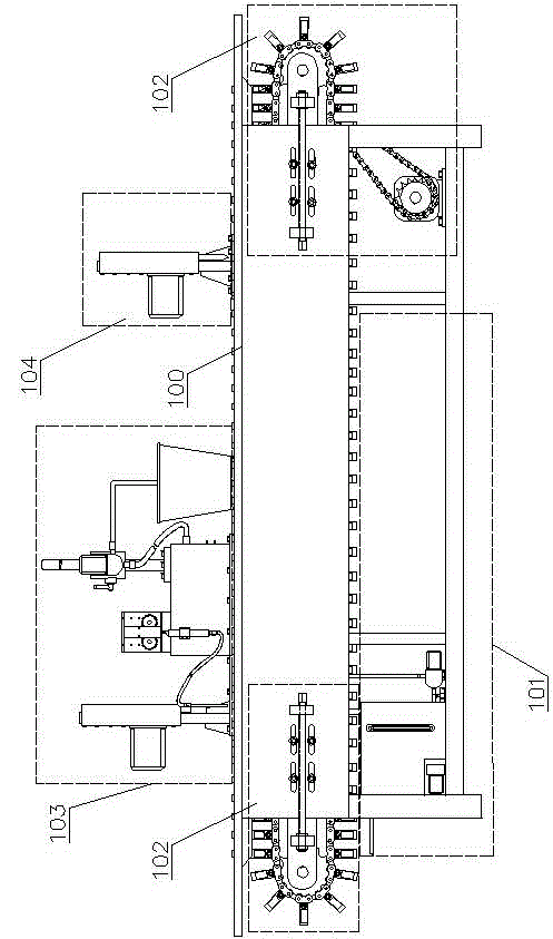
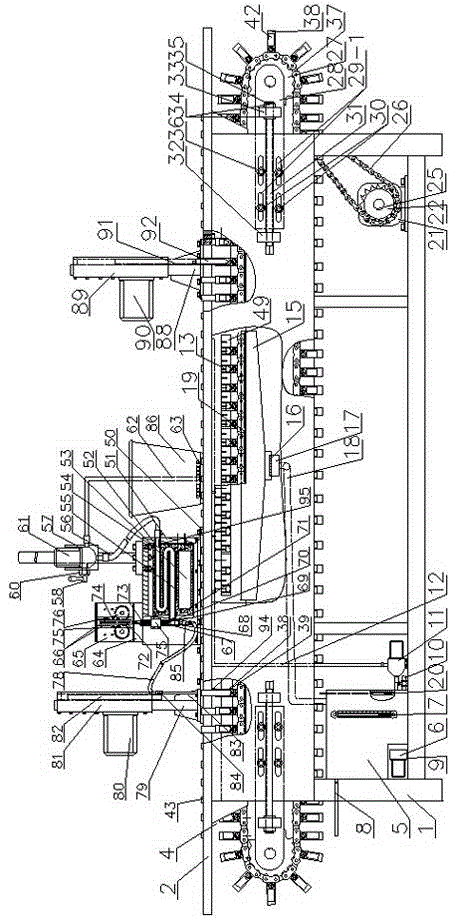
[0037] see Figure 1 ~ Figure 2 , this embodiment includes a machine 100 , a cooling spray device 101 , a transmission device 102 , a glue dispensing device 103 and a forming device 104 .

[0038] Described machine platform 100 comprises frame 1, panel 2, and panel 2 is fixed on the upper end of frame 1, and panel 2 is provided with a conveying trough 4, and the side wall of conveying trough 4 has spray port 19, and the conveying trough Bottom has overflow port 49.

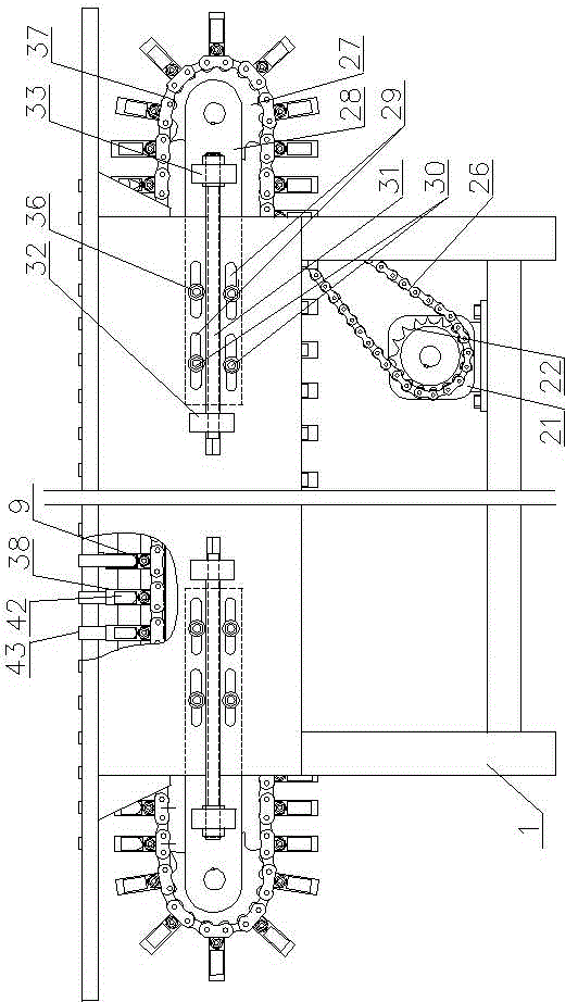
[0039] see Figure 3 ~ Figure 6 , in this embodiment, the transmission device 102 includes a servo motor 21, a No. 1 sprocket 22, a No. 2 sprocket 24, two transmission sprockets 27, two transmission shafts 23, and a blood collection tube sleeve 38. The described The servo motor 21 is fixed on the bottom of the frame 1, the No. 1 sprocket 22 is connected with the servo motor 21, the No. 2 sprocket 24 is inserted into a transmission shaft 23 and fixed, and the No. 1 sprocket 22 and the No. 2 sprocket 24 pass throu...


PUM


Abstract

The invention relates to a full-automatic separation gel injection molding machine for a vacuum blood collection tube. The machine comprises a machine stand, a cooling spraying device, a transmission device, a glue dropping device and a molding device, wherein the machine stand comprises a rack and a panel; the panel is fixed at the upper end of the rack; a conveying groove is formed in the panel; the transmission device is mounted in the rack and comprises a servo motor, a transmission chain and the blood collecting tube; the transmission chain is positioned in the conveying groove; the glue dropping device comprises an attraction assembly, a heating assembly, a glue compaction assembly and a glue dropping assembly which are sequentially connected; a spraying head is arranged on the cooling spraying device and penetrates into the conveying groove; the blood collecting tube in the conveying groove is sprayed and cooled; a molding cone is arranged on the molding device and is used for performing pushing and sizing on the separation gel in the blood collection tube. The machine is reasonable in structural design; automatic integration of gel injection, gel dropping and molding is realized; the separation gel is not polluted, and good blood separation effect is achieved well.

Description

technical field [0001] The invention relates to a fully automatic vacuum blood collection tube glue injection molding machine, which mainly injects separation glue into the blood collection tube, and belongs to the technical field of medical devices. Background technique [0002] Separating gel is an important raw material used in vacuum blood collection tubes. Its function is that the specific gravity of the separating gel is between that of serum and blood cells. The separation gel has high viscosity and is not easy to package at room temperature. According to the blood collection purpose of vacuum blood collection tubes and the national standard, the weight of blood separation gel added to each blood collection tube is 1g±10%. The blood separation glue filling machine in the prior art is a foot-operated semi-automatic blood separation glue filling equipment (patent name: blood separation glue filling machine, patent number: 201010109654.X), the method is: blood The separ...

Claims


Application Information

Patent Timeline
Patent Type & Authority Applications(China)
IPC IPC(8): B29C41/08B29C41/46B29C41/34
Inventor 申屠红华
Owner 杭州拱康医疗科技有限公司
Why Eureka
Try Eureka