
Deep see immersed type tunnel based on rigidity carrier

A submersible and carrier-based technology, applied in the field of deep-sea submersible tunnels based on rigid carriers, can solve the problems of no unified combination design for tunnel functional areas, escape areas and escape areas, large deformation of tunnels, and large flexibility, so as to improve the resistance to ocean currents Action capacity and spanning capacity, increased stiffness, effects of increased longitudinal and transverse stiffness

Active Publication Date: 2015-04-22
NANTONG HAIOU LIFE SAVING & PROTECTION EQUIP
View PDF19 Cites 6 Cited by
  • Summary
  • Abstract
  • Description
  • Claims
  • Application Information

AI Technical Summary

Problems solved by technology

Disadvantages: The fixed connection structure is a steel rope, which is relatively flexible, resulting in large deformation of the tunnel with a long length in the deep sea under the action of laminar or ocean currents
Disadvantages: The structural characteristics of the connecting tunnel are relatively flexible, resulting in large deformation of the long tunnel in the deep sea under the action of laminar or ocean currents. The length of the traction line of the vertical traction anchor has not been considered due to the complex terrain or the distribution of trenches. The seabed caused by the large difference in the length of the traction line caused the tunnel to have a large deformation difference under the action of the sea current
Disadvantages: The structural characteristics of the connecting tunnel are relatively flexible, resulting in large deformation of the tunnel with a long length in the deep sea under the action of laminar or ocean currents
Disadvantages: The structural design and layout of the anchoring system do not take into account the seabed due to the complex terrain or trench distribution
[0009] (1) The flexibility of the anchoring connection system is relatively large, which makes the floating tunnel not suitable for the deep sea with high flow velocity or the seabed with large trenches and complex terrain;
[0010] (2) The design of the tubular tunnel and its support and connection design do not take into account the greater flexibility that will appear when the tunnel length is larger than the pipe diameter;
[0012] (4) There is no unified combination design for the tunnel functional area, escape area and escape area, and the disassembly and replacement of the tunnel body or the port connection and gate layout design during disassembly are not considered
Among the foreign patents mentioned above, 1) and 2) are both Korean patent applications. The biggest feature of the two patents is that they apply the structural characteristics of traditional suspension bridges and cable-stayed bridges to the anchor connection system of floating tunnels. Neither of them considers suspension bridges over water. The difference between the stress characteristics of cables under the action of gravity and the cable-stayed bridge structure under the action of gravity and the stress characteristics of cables under the combined action of gravity, buoyancy and fluid force between underwater suspension bridges and cable-stayed bridge structures, that is, the single-cable plane layout and flexibility of the two The structural features increase the flexibility of the tunnel structure, neither of which is suitable for construction in deep seas, seabeds of large trenches, and areas with complex ocean currents
3) is a French invention patent, which is characterized by the flexible structure of the anchor connection system and the tunnel pipe body connection system. It is intended to increase the flexibility of its own structure to disperse the stress generated under the action of ocean currents, but its structure can only reduce the tunnel superstructure. Capable of long and ultra-deep spans

Method used

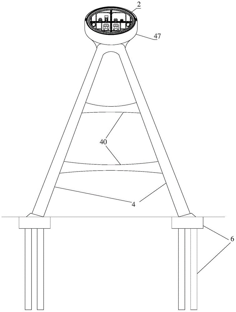
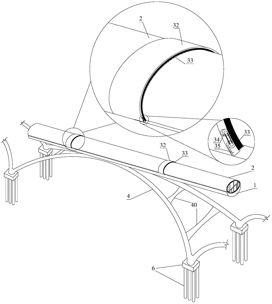

Image

  • Deep see immersed type tunnel based on rigidity carrier
  • Deep see immersed type tunnel based on rigidity carrier
  • Deep see immersed type tunnel based on rigidity carrier

Examples


Embodiment Construction

[0065] Below in conjunction with accompanying drawing and specific embodiment the present invention will be further described;

[0066] A construction method based on the rigid carrier deep-sea submersible tunnel using the above-mentioned design, the specific steps are as follows:

[0067] Step 1: Project preparation, prefabrication of materials and components and construction of lightering wharf in the shore factory, large-scale lightering equipment and underwater construction equipment entering the factory for debugging.

[0068] Step 2: Construction of the foundation 6 of the support structure 3, using an engineering ship to carry out underwater piling construction and underwater pouring of pile foundations and caps;

[0069] Step 3: Construction of the upper structure of the support structure 3, the prefabricated components on the shore are carried out underwater prefabricated and assembled by the engineering ship and the engineering submarine through the cooperation of th...


PUM


Abstract

The invention belongs to deep sea overline transportation and linkage projects, and relates to a deep see immersed type tunnel based on a rigidity carrier. A traditional seabed tunnel, a flume and a bridge are combined and improved, and the immersed type tunnel high in rigidity and capable of being spliced and dismounted is formed. A segment splicing method is adopted in a pipe of the immersed type tunnel, the pipe is embedded in a supporting flume, the pipe can be replaced or dismounted in the later period through a connector at a port of a segment of the tunnel pipe and is transported to the land in a floating mode to be repaired. Water seepage of the tunnel pipe is avoided through a gate at the port of the segment of the tunnel pipe when the part of pipe is dismounted and maintained. Thus, the deep see immersed type tunnel based on the rigidity carrier adapts to deep sea and has high spanning capability through increasing of the structural carrier rigidity and has the dismounting and replacing functions.

Description

technical field [0001] The invention relates to a deep-sea submersible tunnel based on a rigid carrier, which combines and improves traditional subsea tunnels, aqueducts and bridges to form a highly rigid submersible tunnel that can be assembled and disassembled. The invention relates to a rigid carrier-based deep-sea submersible tunnel, which belongs to the technical field of deep-sea elevated tunnels, underwater floating tunnels, submarine suspension pipelines and deep-sea pipes and culverts. The structural features of the invention include a tunnel body, a tunnel carrier, a supporting structure and a connecting device. The technical features of the present invention can not only effectively increase the stiffness of the submersible tunnel in the sea and avoid excessive deformation caused by deep-sea laminar currents or ocean currents, but also increase the spanning capacity of the submersible tunnel, making the submersible tunnel applicable On rugged seabeds or deep trench...

Claims


Application Information

Patent Timeline
Patent Type & Authority Applications(China)
IPC IPC(8): E02D29/067
CPCE02D29/067
Inventor 陈壮张文学汪振刘啸
Owner NANTONG HAIOU LIFE SAVING & PROTECTION EQUIP
Learn More