
Storage and emergency supply device and method for standby instrument gas source

A technology of backup instrument and supply device, which is applied in the field of storage and emergency supply device for providing backup instrument gas source, can solve the problems of many supporting facilities, high pressure of medium-pressure purified compressed air storage tank 103, consumption of water and electricity, etc. Avoid material consumption, reduce equipment investment, and reduce the effect of supporting facilities

Active Publication Date: 2015-04-22
BEIJING PETROCHEM ENG
View PDF6 Cites 6 Cited by
  • Summary
  • Abstract
  • Description
  • Claims
  • Application Information

AI Technical Summary

Problems solved by technology

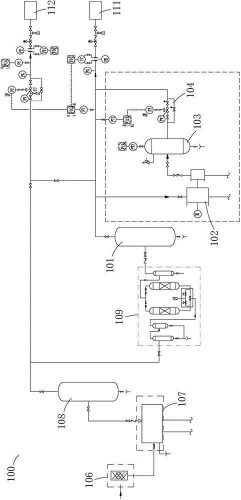
[0005] 1. Large area: A purified compressed air compressor 102 is large in size, and generally needs to occupy a workshop area of ​​12 meters by 6 meters after installation, and the volume of the medium-pressure purified compressed air storage tank 103 is generally large;
[0006] 2. High investment: not only the cost of the purified compressed air compressor 102 is high, but also the medium-pressure purified compressed air storage tank 103 is expensive due to its high pressure and large volume;
[0007] 3. There are many supporting facilities and high consumption: the compressor needs to be equipped with supporting water supply, power supply and workshop, and it will also consume water and electricity

Method used


Image

  • Storage and emergency supply device and method for standby instrument gas source
  • Storage and emergency supply device and method for standby instrument gas source
  • Storage and emergency supply device and method for standby instrument gas source

Examples


Embodiment Construction

[0039] The above and other technical features and advantages of the present invention will be clearly and completely described below in conjunction with the accompanying drawings. Apparently, the described embodiments are only some of the embodiments of the present invention, not all of them.

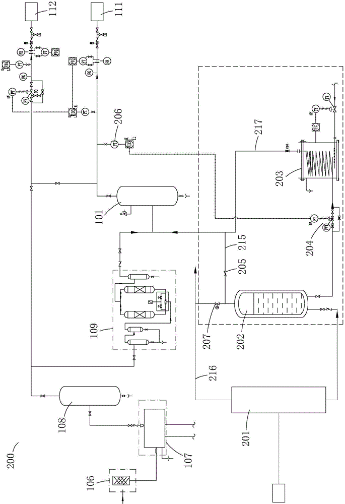
[0040] see figure 2 As shown, it is a schematic structural diagram of the storage and emergency supply device of the standby instrument gas source of the present invention, a storage and gasification equipment, including a liquid nitrogen storage tank 202 connected in series through pipelines, a control valve group 204 and a gasifier 203; storage and gasification equipment such as figure 2 shown in the dotted box. The liquid nitrogen in the liquid nitrogen storage tank 202 is input into the gasifier 203 through the opened control valve group 204, and the gasifier 203 has an output port.

[0041] The invention adopts liquid nitrogen as the storage mode of the backup instrument gas so...


PUM


Abstract

The invention provides a storage and emergency supply device and method for a standby instrument gas source. The device comprises a storage and gasification device, a nitrogen making machine and a buffer tank. The storage and gasification device comprises a liquid nitrogen storage tank, a control valve unit and a vaporizer. The liquid nitrogen storage tank, the control valve unit and the vaporizer are sequentially connected in series through a pipeline. Liquid nitrogen in the liquid nitrogen storage tank is input to the vaporizer through the opened control valve unit, and the vaporizer is provided with an output port. The nitrogen making machine is provided with the inlet and a liquid nitrogen outlet. The liquid nitrogen outlet is connected with an inlet of the liquid nitrogen storage tank through a pipeline. The outlet of the buffer tank is connected with an external purified compressed air pipe network through a pipeline. The inlet of the buffer tank is connected with the output port of the vaporizer through a gas supply pipeline. The purified compressed air pipe network is provided with an air pressure sensor used for transmitting signals of air pressure values of the purified compressed air pipe network, and the control valve unit is controlled to be opened and closed through the output signals of the air pressure sensor. Compared with a conventional device and method, the investment is low, the occupied area is small and public and auxiliary consumption is avoided.

Description

technical field [0001] The invention relates to the technical field of air compressor stations in petrochemical plants, in particular to a storage and emergency supply device and method for providing backup instrument gas sources. Background technique [0002] In petrochemical production, instrument control valves are mostly adjusted and controlled by pneumatic actuators. Therefore, the continuous and stable air supply of air compressor stations plays a vital role in the safe production of petrochemical plants. In order to ensure the safe gas supply of instrument gas source, SH3020 "Petrochemical Instrument Gas Supply Design Code" requires that a backup gas source should be set up, and it is clearly stipulated that the maintenance time of instrument gas source should be based on the production scale, the complexity of the process and the safety interlock It is determined by the level of automatic protection design. If there is no special requirement, the maintenance time of ...

Claims


Application Information

Patent Timeline
Patent Type & Authority Applications(China)
IPC IPC(8): F17C5/06F17C13/02F17C13/04
Inventor 李奎刘戈
Owner BEIJING PETROCHEM ENG
Learn More