Large-diameter parallel light pipe wavefront and image surface position calibration device and method

A technology of collimating light pipe and image plane position, applied in the direction of testing optical performance, etc., can solve the problems of large measurement error, rising mirror material and processing cost, and inability to accurately measure the mirror surface type, so as to eliminate chromatic aberration and improve interpretation accuracy. Effect

Inactive Publication Date: 2015-04-22
XI'AN INST OF OPTICS & FINE MECHANICS - CHINESE ACAD OF SCI
View PDF7 Cites 11 Cited by
  • Summary
  • Abstract
  • Description
  • Claims
  • Application Information

AI Technical Summary

Problems solved by technology

The existing problem is that when the aperture of the light pipe increases, the aperture of the reflector also increases accordingly, and the surface shape of the reflector itself cannot be accurately measured. In addition, the material and processing costs of the reflector are also doubled, and the measurement method is affected by the environment and human subjectivity. Sexual influences lead to large measurement errors

Method used


Image

  • Large-diameter parallel light pipe wavefront and image surface position calibration device and method
  • Large-diameter parallel light pipe wavefront and image surface position calibration device and method

Examples


Embodiment Construction

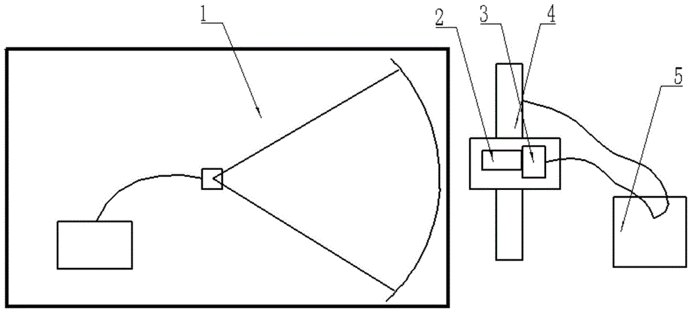
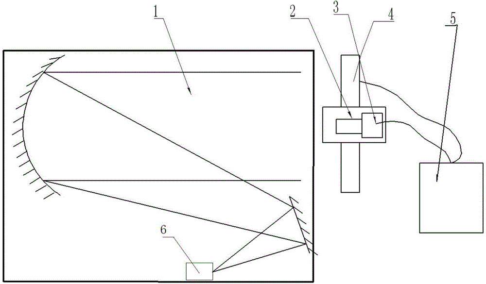
[0038] This paper proposes a new detection device and method to solve the detection of the accuracy of the wavefront and focal plane position of the large aperture collimator.

[0039] Such as figure 1 As shown: the device includes a fiber laser 1, a two-dimensional precision long guide rail 4, an optical lens 2, a CCD detector 3 and a computer 5;

[0040] The optical lens 2 and the CCD detector 3 are precisely connected to form a CCD camera.

[0041] The CCD camera is installed on the two-dimensional precision long guide rail 4; the two-dimensional precision long guide rail 4 includes a horizontal guide rail and a vertical guide rail installed on the horizontal guide rail; the CCD camera can move horizontally and vertically along the two-dimensional precision long guide rail 4; The laser 1 is located directly in front of the CCD camera; the control unit is respectively connected with the two-dimensional precision long guide rail 4 and the CCD camera.

[0042] The control un...


PUM


Abstract

The invention belongs to the field of photoelectricity testing and relates to a large-diameter parallel light pipe wavefront and image surface position calibration device and method. The device comprises a fiber laser, a two-dimension precision long guiding track, a CCD camera and a control unit. The method comprises the steps that (1) the CCD camera is arranged on the two-dimension precision long guiding track; (2) fiber laser power is adjusted until the CCD camera can receive fiber laser light intensity; (3) the CCD camera obtains center-of-mass coordinates of image points emitted by the fiber laser at different positions of the two-dimension precision long guiding track; (4) the CCD camera obtains center-of-mass coordinates of image points emitted by a parallel light pipe to be calibrated at different positions of the two-dimension precision long guiding track; (5) the wavefront position of the parallel light pipe to be calibrated is determined; and (6) the image surface position of the parallel light pipe to be calibrated is determined. Accurate testing of large-diameter parallel light pipe wavefront and focal plane positions can be achieved.

Description

technical field [0001] The invention belongs to the field of photoelectric testing, and relates to a device and method for calibrating wavefront and image plane positions of a large-diameter collimator. Background technique [0002] The collimator is an optical precision measurement device used to simulate an infinite target in the laboratory, emit parallel light beams, and measure the imaging quality and performance parameters of an optical system or camera. [0003] In recent years, due to the rapid development of my country's aerospace and aviation technology, especially the implementation of high-resolution projects, the imaging quality and ground resolution of space cameras have become higher and higher, and the focal length and aperture of cameras have also become larger and larger. Therefore, it is required to detect the optical precision measurement equipment of long focal length, large-aperture camera imaging quality and performance parameters-the aperture and focal ...

Claims


Application Information

Patent Timeline
Patent Type & Authority Applications(China)
IPC IPC(8): G01M11/02
Inventor 赵建科周艳李霞徐亮陈永权
Owner XI'AN INST OF OPTICS & FINE MECHANICS - CHINESE ACAD OF SCI
Why Eureka
Try Eureka