Window-scanning thermal imaging defect detecting and tomography method and system

A defect detection and tomography technology, which is used in structural health monitoring and product quality control, material characterization evaluation, and equipment non-destructive testing. It can solve problems such as poor detection effect, inability to perform tomography, and inability to obtain temperature change information.

Active Publication Date: 2015-04-22
何赟泽
View PDF5 Cites 32 Cited by
  • Summary
  • Abstract
  • Description
  • Claims
  • Application Information

AI Technical Summary

Problems solved by technology

The main disadvantages of the static detection method are: 1) It is necessary to configure the position of the thermal imager multiple times to detect large objects, the detection efficiency is low, and the detection time is long; 2) The heat source is heated unevenly, resulting in poor imaging and defect detection results
However, the existing thermal imaging motion detection methods have certain deficiencies: 1) Using the temperature value of a column of pixels for imaging can only display temperature information at a certain moment, and cannot perform tomographic imaging; 2) Using the temperature collected by a thermal imager 3) It is impossible to obtain the temperature change information of each point of the inspected object, and it is difficult to use thermal wave theory and advanced digital signal processing methods for in-depth analysis

Method used


Image

  • Window-scanning thermal imaging defect detecting and tomography method and system
  • Window-scanning thermal imaging defect detecting and tomography method and system
  • Window-scanning thermal imaging defect detecting and tomography method and system

Examples


Embodiment Construction

[0047] Specific embodiments of the present invention will be described below in conjunction with the accompanying drawings, so that those skilled in the art can better understand the present invention.

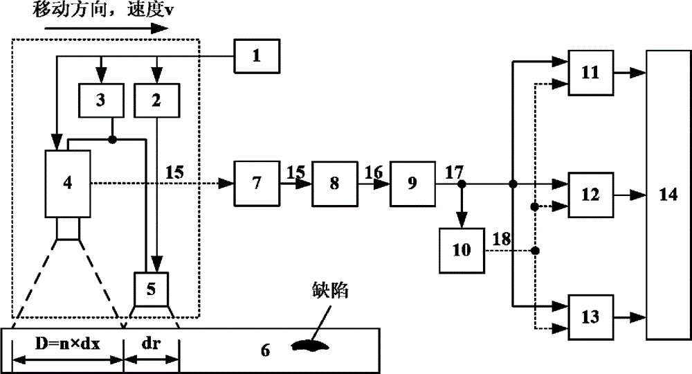
[0048] figure 1 It is a schematic diagram of a window-scanning thermal imaging defect detection and tomographic imaging system, which mainly includes: controller 1, heat source control module 2, scanning module 3, thermal imager 4, heat source 5, inspected object 6, computer 7, data registrar Construction module 8, detection signal extraction module 9, reference signal setting module 10, time domain algorithm module 11, frequency domain algorithm module 12, cross-correlation algorithm module 13, defect detection and tomography module 14, etc. It should be noted that the controller 1 can be a real object, or software running on a computer 7; the heat source 5 can be heat sources such as hot air, a flash light source, a laser source, an electromagnetic source, a microwave source...


PUM


Abstract

The invention discloses window-scanning thermal imaging defect detecting and tomography method and system. When the system works, a detected objected is scanned by a heat source and a thermal imager at fixed speed and is heated by the heat source, and temperature information varied along the time after the surface of the detected objected is heated is recorded by the thermal imager as original data; the original data is reconstructed to acquire a temperature variation sequence of each point of the detected objected as a detection signal; a specific signal is utilized or produced as a reference signal; the detection signal and the reference signal are processed by virtue of methods such as time domain, frequency domain and mutual correlation; a time domain feature value, a frequency domain feature value, a mutual correlation amplitude feature value and a mutual correlation phase feature value are extracted, and therefore, the defect detection and the tomography are achieved. The method and the system can be applied to the nondestructive testing of devices, the characterization assessment of materials and the quality control of products in the fields of aerospace, new materials, petrochemical engineering, nuclear power, railways, automobiles, special equipment, machinery, metallurgy and civil construction.

Description

technical field [0001] The invention belongs to the technical fields of equipment non-destructive testing, material characterization evaluation, structural health monitoring and product quality control, and in particular relates to a thermal imaging detection method and system. Background technique [0002] With the development of modern science and industrial technology, non-destructive testing technology has become a necessary means to ensure product quality and equipment operation safety. At present, representative non-destructive testing technologies mainly include radiographic testing, ultrasonic testing, penetrant testing, magnetic particle testing, eddy current testing, and thermal imaging testing. [0003] Thermal imaging detection technology uses a heat source to heat the object to be inspected, and uses a thermal imager to observe and record the temperature change information on the surface of the object to be inspected, so as to detect and evaluate the surface and...

Claims


Application Information

Patent Timeline
Patent Type & Authority Applications(China)
IPC IPC(8): G01N25/72
Inventor 何赟泽杨瑞珍
Owner 何赟泽
Why Eureka
Try Eureka