High-specific stiffness supporting structure of space optical remote sensor

A space optical remote sensing and support structure technology, applied in the field of space optics, can solve problems such as general stability, high support structure weight, and low natural frequency, and achieve the effects of low weight, increased stiffness, and high specific stiffness

Inactive Publication Date: 2015-04-22
CHANGCHUN INST OF OPTICS FINE MECHANICS & PHYSICS CHINESE ACAD OF SCI
View PDF3 Cites 18 Cited by
  • Summary
  • Abstract
  • Description
  • Claims
  • Application Information

AI Technical Summary

Problems solved by technology

[0005] The purpose of the present invention is to provide a support structure for space optical remote sensors with high specific stiffness, which solves

Method used


Image

  • High-specific stiffness supporting structure of space optical remote sensor
  • High-specific stiffness supporting structure of space optical remote sensor
  • High-specific stiffness supporting structure of space optical remote sensor

Examples


Embodiment Construction

[0019] The present invention will be further elaborated below in conjunction with the accompanying drawings.

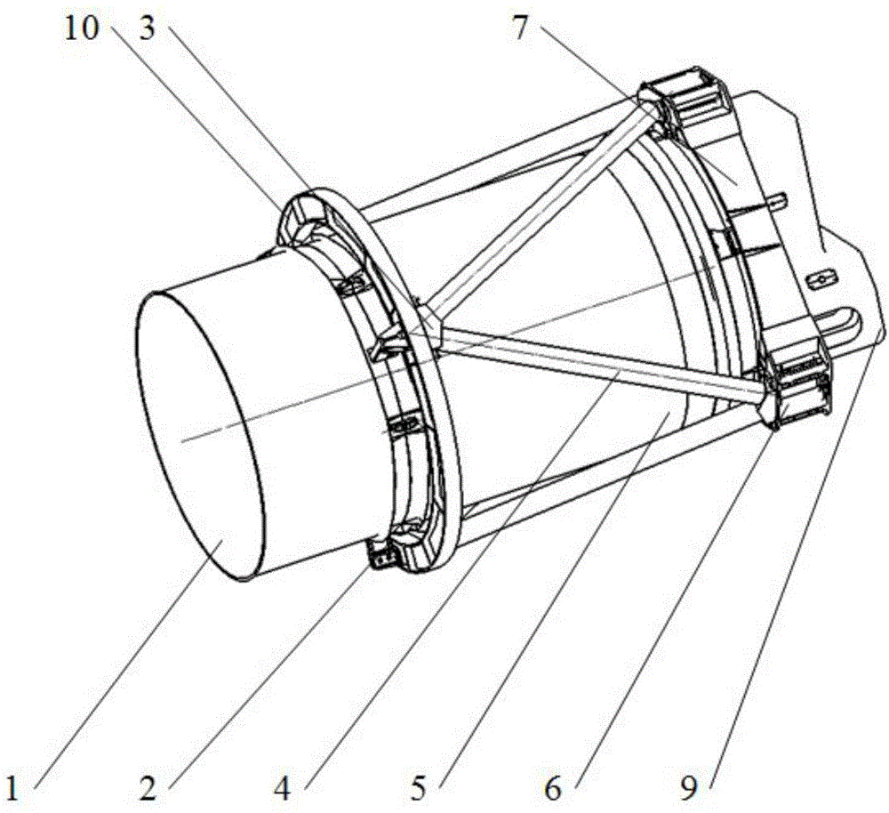
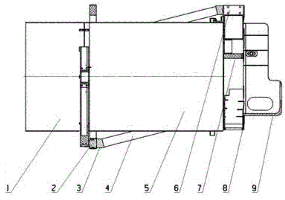
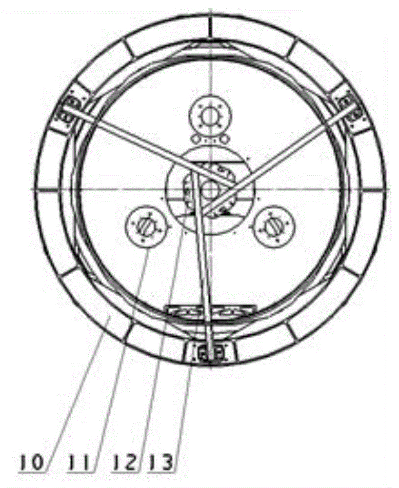
[0020] See attached figure 1 , attached figure 2 And attached image 3 , a high specific stiffness space optical remote sensor support structure of the present invention includes an outer light shield group, a truss assembly and a main backboard assembly;

[0021] The outer hood assembly includes a carbon fiber front cylinder 1 and a carbon fiber rear cylinder 5, and the carbon fiber front cylinder 1 is connected to the carbon fiber rear cylinder 5 by screws;

[0022] The truss assembly includes a secondary mirror embedded part 12, a carbon fiber secondary mirror bracket 13, a carbon fiber support ring 10, a plurality of support ring embedded parts 2, a plurality of truss rod joints 3 and a plurality of carbon fiber truss rods 4; the secondary mirror embedded part 12 Pasted on the middle of the carbon fiber secondary mirror bracket 13, the secondary mirror bracket...


PUM


Abstract

The invention discloses a high-specific stiffness supporting structure of a space optical remote sensor, and belongs to the technical field of space optics. The supporting structure solves the problems that in the prior art, a supporting structure of the space optical remote sensor is heavy, poor in stability and low in inherent frequency. The supporting structure comprises a carbon fiber front cylinder, a carbon fiber rear cylinder, a secondary mirror embedded part, a carbon fiber secondary mirror support, a carbon fiber supporting ring, a plurality of supporting ring embedded parts, truss rod connectors, a plurality of carbon fiber truss rods, truss embedded parts, a carbon fiber matrix, primary mirror assembly embedded parts, a three-mirror embedded part and a carbon fiber rear cover. The carbon fiber front cylinder is connected to the carbon fiber rear cylinder, the secondary mirror embedded part adheres to the middle of the carbon fiber secondary mirror support, the supporting ring embedded parts are circumferentially and uniformly distributed on the carbon fiber supporting ring, the front ends of the carbon fiber truss rods are connected to the back surface of the carbon fiber supporting ring, the rear ends of the carbon fiber truss rods are connected to the truss embedded parts of a main backboard assembly, and the carbon fiber rear cover, the truss assembly embedded parts, the three-mirror assembly embedded part and the primary mirror assembly embedded parts are connected to the carbon fiber matrix.

Description

technical field [0001] The invention belongs to the technical field of space optics, and in particular relates to a support structure for a space optical remote sensor with high specific stiffness. Background technique [0002] Space optical remote sensors are widely used in many fields such as detailed survey and census of earth resources, topographic surveying and mapping, ocean research, urban construction, agricultural development, weather forecast, military reconnaissance, etc. Space optical remote sensors will be tested by various external loads and environmental conditions such as vibration, shock and noise during the development, testing and launch stages on the ground. Among them, the dynamic environment has the greatest impact on the remote sensor. The dynamic loads on the remote sensor mainly include accidental shocks and explosion shocks caused by adjustment and experimentation, ground transportation, separation of the fairing of the launch vehicle, separation o...

Claims


Application Information

Patent Timeline
IPC IPC(8): G02B7/00G02B7/182
CPCG02B7/00G02B7/182
Inventor 金光张雷贾学志安源徐振
Owner CHANGCHUN INST OF OPTICS FINE MECHANICS & PHYSICS CHINESE ACAD OF SCI
Why Eureka
Try Eureka