Roll arrangement
A roll and roll neck technology, applied in the field of rolling equipment, can solve problems such as large size, and achieve the effect of improving load capacity
- Summary
- Abstract
- Description
- Claims
- Application Information
AI Technical Summary
Problems solved by technology
Method used
Image

Examples
Embodiment Construction
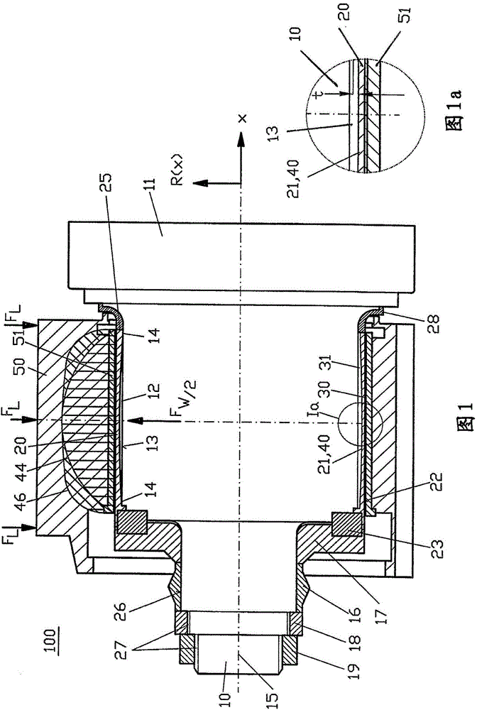
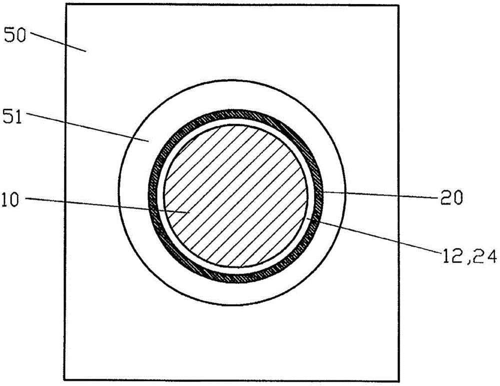
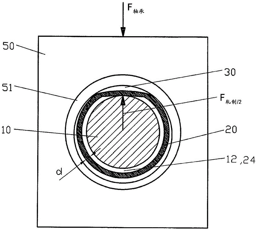
[0030] exist figure 1 shows a rolling installation 100 , for example used in metallurgy, which has a roll with a roll body 11 and at least one cylindrical roll neck 10 . The roll neck 10 is mounted in a rotationally fixed manner with radial play in a receiving bore of a roll neck bushing 20 which is complementary to the roll neck 10 and has a cylindrical shape. The radial gap between the roll neck bushing 20 and the roll neck 10 is formed by the hollow space 12 which is rotationally symmetrical or surrounds the roll neck 10 . Through the radial play, the roll neck bushing 20 can easily be pushed onto the roll neck 10 or conversely the roll neck 10 can be pushed into the roll neck bushing 20 . The radial play as a diameter difference between the roll neck bushing 20 and the roll neck 10 is preferably in the range between 0.10 mm and 0.80 mm at the most.
[0031] The wall thickness d of the cylindrical roll neck bushing is between 10 mm and 75 mm, without taking into account ...
PUM
 Abstract
Description
Claims
Application Information
 - Generate Ideas
- Intellectual Property
- Life Sciences
- Materials
- Tech Scout
- Unparalleled Data Quality
- Higher Quality Content
- 60% Fewer Hallucinations
Browse by: Latest US Patents, China's latest patents, Technical Efficacy Thesaurus, Application Domain, Technology Topic, Popular Technical Reports.
© 2025 PatSnap. All rights reserved.Legal|Privacy policy|Modern Slavery Act Transparency Statement|Sitemap|About US| Contact US: help@patsnap.com