Ultrasonic device for cleaning denitration catalyst

A technology for denitrification catalysts and out-of-stock catalysts, which is applied in the field of ultrasonic devices for cleaning denitrification catalysts. It can solve the problems of uncleaning, attenuation, and low regeneration quality in the central area, and achieve good regeneration quality, good cleaning effect, and uniform energy distribution.

Inactive Publication Date: 2015-04-29
CHENGDU JIUZHOU LIYUAN TECH
View PDF3 Cites 4 Cited by
  • Summary
  • Abstract
  • Description
  • Claims
  • Application Information

AI Technical Summary

Problems solved by technology

This device has great disadvantages: first, the ultrasonic energy is severely attenuated inside the denitrification catalyst, resulting in the inside of the workpiece, especially the central area, which cannot be cleaned, and the cleaning effect is poor; The strength of the denitrification catalyst is greatly reduced, resulting in structural damage; the third is the existing denitrification catalyst ultrasonic cleaning device, the ultrasonic wave emits energy in an axial manner, and the cleaning effect is poor; the fourth is the existing denitrification catalyst ultrasonic device, the ultrasonic wave is in the denitrification catalyst. The energy distribution in the workpiece is uneven, and the regeneration quality is not high, which directly affects the use effect and life of the regenerated denitration catalyst

Method used


Image

  • Ultrasonic device for cleaning denitration catalyst
  • Ultrasonic device for cleaning denitration catalyst

Examples


Embodiment 1

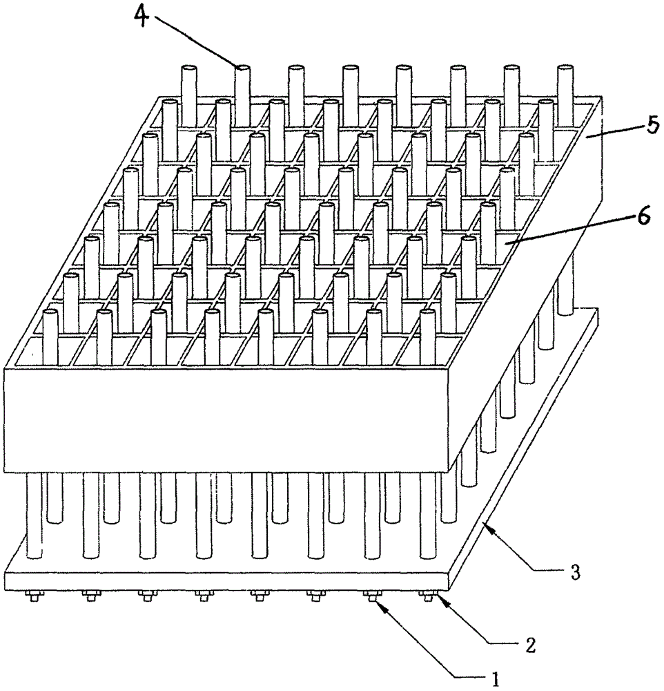
[0016] Such as figure 1 The ultrasonic device for cleaning the denitration catalyst shown includes an ultrasonic generator 1 , an ultrasonic rod 4 and a porous flange 3 . The ultrasonic generator 1 is connected to the ultrasonic rod 4, and the ultrasonic rod 4 is one or more than one. The ultrasonic rods 4 are arranged in parallel, and the gap between the ultrasonic rod 4 and the hole 6 is matched. One end of the rod 4 is connected with the porous flange 3 through the fixing nut 2, and the ultrasonic rod 4 can be made of titanium alloy or rare earth titanium alloy or stainless steel or aluminum alloy.

[0017] When in use, take an invalid denitrification catalyst module, put it into the ultrasonic cleaning device after vacuuming with negative pressure, insert the ultrasonic rod into the hole of the denitrification catalyst to clean the inside of the denitrification catalyst, and the ultrasonic generator emits ultrasonic waves (the frequency is 16KHZ-100000KHZ), the direction ...

Embodiment 2

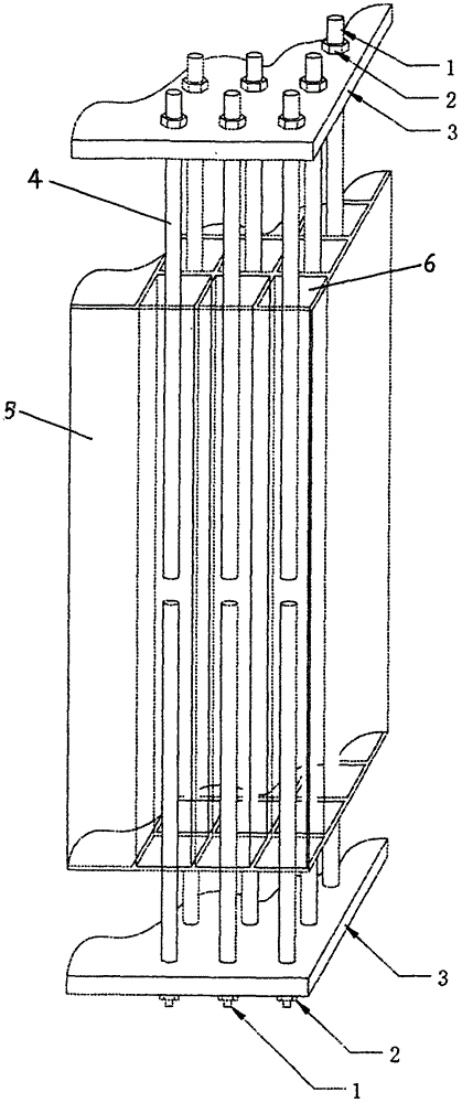
[0019] Such as figure 2 The ultrasonic device for cleaning the denitration catalyst shown includes an ultrasonic generator 1 , an ultrasonic rod 4 and a porous flange 3 . The ultrasonic generator 1 is connected to the ultrasonic rod 4, and the ultrasonic rod 4 is one or more than one. The ultrasonic rods 4 are arranged in parallel, and the gap between the ultrasonic rod 4 and the hole 6 is matched. Insert, one end of each ultrasonic rod 4 extends out of the hole of the denitration catalyst 5 and is connected with the porous flange 3 through the fixing nut 2, and the other end is in the hole 6, and the ultrasonic rod 4 can be titanium alloy or rare earth titanium alloy or stainless steel or made of aluminum alloy.

[0020] When in use, take an invalid denitrification catalyst module, put it into the ultrasonic cleaning device after vacuuming with negative pressure, insert the ultrasonic rod into the hole of the denitrification catalyst to clean the inside of the denitrificati...


PUM


Abstract

The invention relates to an ultrasonic device for cleaning a denitration catalyst. The device comprises an ultrasonic generator, one or more than one ultrasonic bars and a porous flange plate, wherein the ultrasonic generator is connected with the ultrasonic bars; the multiple ultrasonic bars are arranged in parallel; the ultrasonic bars are inserted into the holes of the denitration catalyst; each ultrasonic bar can be inserted into the hole of the denitration catalyst from one end or two ends of the denitration catalyst; and one end of each ultrasonic bar is connected with the porous flange plate. The device disclosed by the invention is good in cleaning effect, and the ultrasonic bars stretch into the interiors of the holes of the catalyst for cleaning; the ultrasonic energy distribution is uniform, and structural damage of the catalyst is avoided; and moreover, the ultrasonic energy emission is mainly performed in the radial direction, the pores are completely cleaned, and the catalyst is high in regeneration quality, stable and reliable.

Description

technical field [0001] The invention relates to an ultrasonic device, in particular to an ultrasonic device for cleaning a denitrification catalyst. Background technique [0002] China is a country that consumes a lot of energy mainly by thermal power. It emits a large amount of nitrogen oxides while burning coal. If the control is not strengthened, the consequences of air pollution in our country will become more and more serious. According to the data provided by the China Environmental Monitoring Center, in 2011 my country's total nitrogen oxide emissions were 24.043 million tons, of which the power industry's nitrogen oxide emissions accounted for more than 45%, accounting for more than half of the total emissions of various combustion devices, while the power industry More than 80% of the nitrogen oxides emitted by the industry are emitted by coal-fired boilers. . [0003] In order to reduce nitrogen oxide emissions, there are two ways of combustion process control and...

Claims


Application Information

Patent Timeline
Patent Type & Authority Applications(China)
IPC IPC(8): B01D53/96B01D53/56B01J38/48
Inventor 邓令魏昭荣罗显刚韦巍
Owner CHENGDU JIUZHOU LIYUAN TECH
Why Eureka
Try Eureka