Manufacturing method of fiber

A manufacturing method and optical fiber technology, applied in the field of optical fiber manufacturing, can solve problems such as the increase of the outer diameter variation of the optical fiber, and achieve the effects of suppressing the outer diameter variation, reducing the natural convection, and reducing the pressure variation.

Inactive Publication Date: 2015-04-29
SUMITOMO ELECTRIC IND LTD
View PDF7 Cites 10 Cited by
  • Summary
  • Abstract
  • Description
  • Claims
  • Application Information

AI Technical Summary

Problems solved by technology

This phenomenon does not easily occur when helium gas with high thermal conductivity is used as the gas in the furnace, but it easily occurs in the case of argon gas, nitrogen gas, etc. The outer diameter variation of the optical fiber increases

Method used


Image

  • Manufacturing method of fiber
  • Manufacturing method of fiber
  • Manufacturing method of fiber

Examples


Embodiment Construction

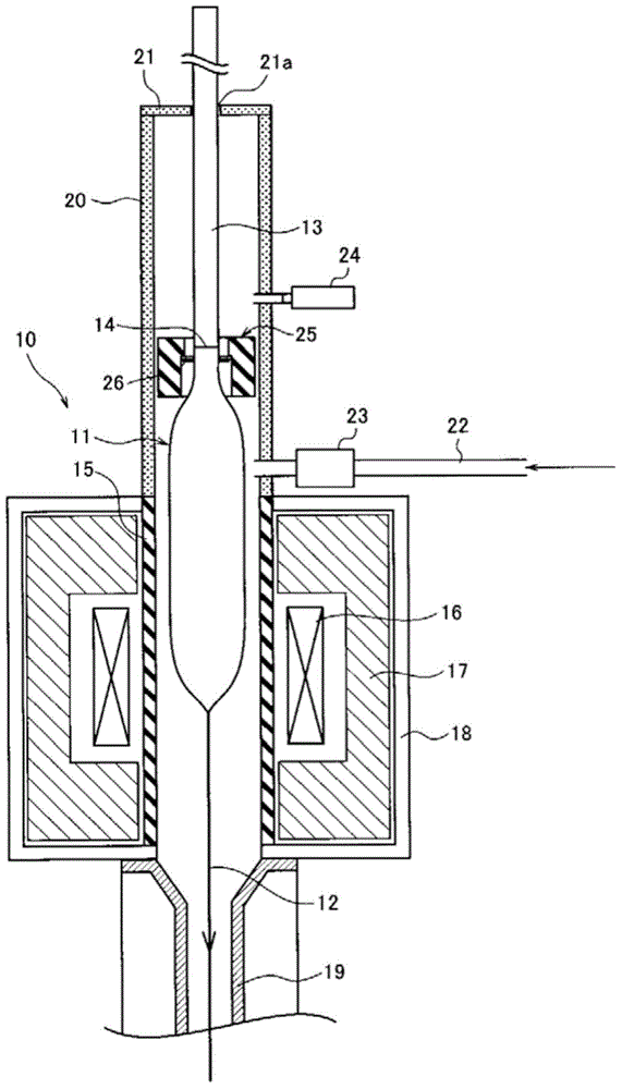
[0018] figure 1 It is a schematic diagram of the drawing furnace 10 used in the manufacturing method of the optical fiber of this invention. Hereinafter, a resistance furnace in which a core tube is heated by a heater will be described as an example, but the present invention can also be applied to an induction furnace in which a core tube is heated by induction by applying a high-frequency power supply to a winding.

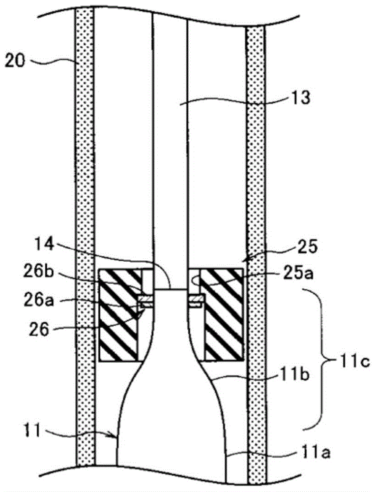
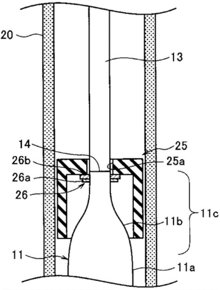
[0019] The wire drawing furnace 10 is composed of a furnace housing 18 , a lower chamber 19 , and an upper chamber 20 . The furnace core tube 15 is formed in a cylindrical shape at the center of the furnace housing 18 and communicates with the lower chamber 19 and the upper chamber 20 . The furnace core tube 15 is made of carbon, and a glass base material 11 for an optical fiber (hereinafter referred to as a glass base material) is inserted into the furnace core tube 15 through the upper chamber 20 .

[0020] The upper chamber 20 has, for example, an inner dia...


PUM


Abstract

The invention provides a manufacturing method of a fiber. By reducing pressure variation and gas flow variation of a fiber drawing furnace resulting from fiber drawing operation of glass base material so that a variation in the external diameter of the fiber is inhibited to be smaller. The manufacturing method is described in that the upper end of the glass base material (11) for the fiber with a necking portion (11c) at the upper portion is connected with a support rod (13); the fiber is formed by being drawn out through heating and melting of the glass base material for the fiber in the fiber drawing furnace; and the position where the necking portion of the glass base material for the fiber is provided with a part (25), the size of which is larger than or equal to 50% of space between the necking portion and a fuel core pipe so that the fiber is drawn out.

Description

technical field [0001] The invention relates to an optical fiber manufacturing method in which a support rod is connected to a constricted portion at the upper end of a glass base material for an optical fiber, and the glass base material for an optical fiber is heated and melted in a drawing furnace to draw an optical fiber. Background technique [0002] Optical fiber drawing is performed by heating and melting an optical fiber glass base material (hereinafter referred to as glass base material) mainly composed of silica using a heater or the like in an optical fiber drawing furnace (hereinafter referred to as drawing furnace). At this time, the temperature in the drawing furnace is about 2000°C, which is very high, so carbon with better heat resistance is used for the parts in the drawing furnace. This carbon has a property of being oxidized and consumed in a high-temperature oxygen-containing atmosphere. Therefore, it is necessary to maintain an atmosphere of rare gas su...

Claims


Application Information

Patent Timeline
Patent Type & Authority Applications(China)
IPC IPC(8): C03B37/025
Inventor 小西达也冈崎岩山崎卓
Owner SUMITOMO ELECTRIC IND LTD
Why Eureka
Try Eureka