Manifold for vacuum evaporation apparatus

A vapor deposition and manifold technology, which is applied to the field of manifolds for vacuum vapor deposition devices, can solve the problems of unstable film thickness distribution of vapor deposition materials, reduced conductivity of ejection channels, and difficulty in approaching nozzle openings. The vapor deposition distance is shortened, the uniformity is not deteriorated, and the vapor deposition rate is improved.

Active Publication Date: 2015-04-29
HITACHI ZOSEN CORP
View PDF12 Cites 3 Cited by
  • Summary
  • Abstract
  • Description
  • Claims
  • Application Information

AI Technical Summary

Problems solved by technology

When the deposition distance is shortened, in order to ensure the uniformity of the deposited film thickness, it is necessary to increase the number of nozzle openings, so that the ejection nozzles are close to each other.
In addition, in order to adjust the discharge amount, the nozzle opening of the discharge nozzle is an orifice whose outlet is narrowed. The film thickness distribution of the vapor deposition material sprayed from the nozzle is unstable
Therefore, it is difficult to place the nozzle opening close to
[0006] As a countermeasure, the diameter of the nozzle opening can be reduced, but if the diameter of the nozzle opening is reduced, the conductivity of the discharge flow path will be reduced
Therefore, in order to ensure a predetermined evaporation rate, it is necessary to increase the evaporation temperature (heating temperature) of the evaporation material in the crucible, but if the evaporation temperature is raised, some evaporation materials are likely to deteriorate, and there is a possibility that the operating cost will increase.

Method used


Image

  • Manifold for vacuum evaporation apparatus
  • Manifold for vacuum evaporation apparatus
  • Manifold for vacuum evaporation apparatus

Examples


Embodiment 1

[0029] Next, Embodiment 1 of a manifold for an in-line vapor deposition system vacuum vapor deposition apparatus according to the present invention will be described based on FIGS. 1 to 4 .

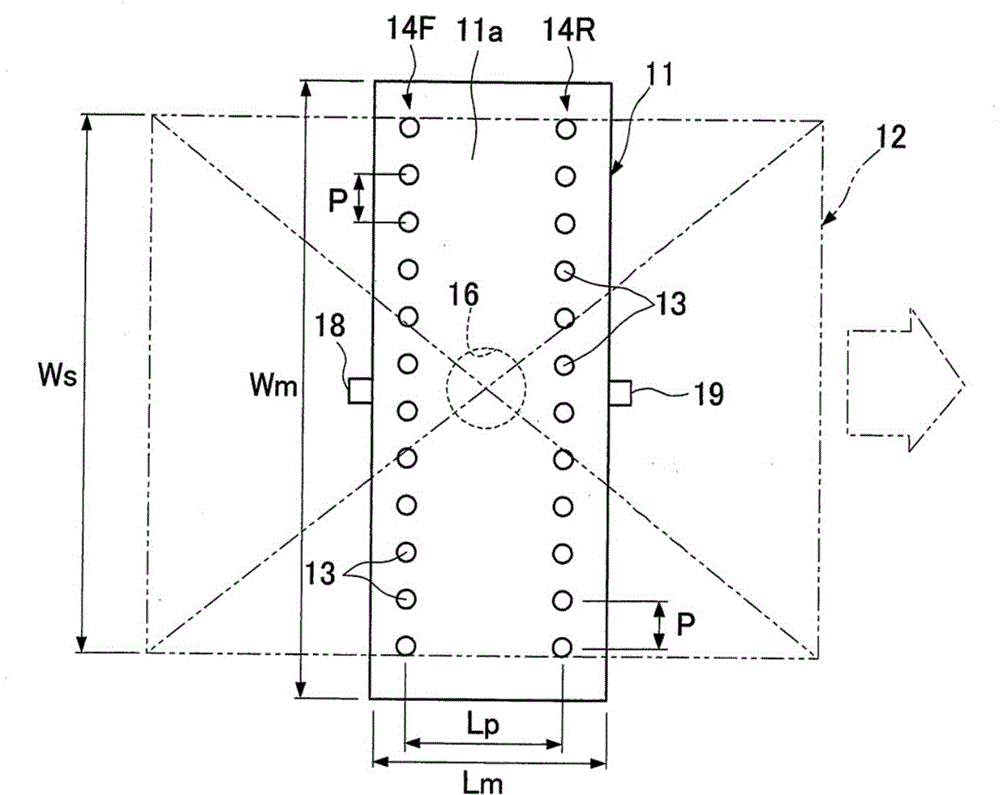
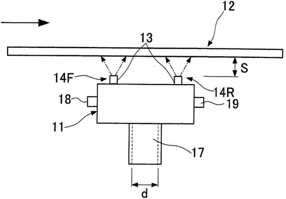
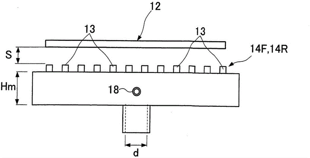
[0030] Figure 1, figure 2 As shown, in a vacuum evaporation chamber maintained in a vacuum state, the manifold 11 is arranged facing the surface to be evaporated of a substrate (substrate to be evaporated) 12 moving at a constant speed. On the opposing surface 11a of the manifold 11, nozzle rows 14F, 14R are respectively provided in the front and rear of the moving direction of the substrate 12, and the plurality of ejection nozzles 13 of the nozzle rows 14F, 14R are arranged in a predetermined nozzle pattern along the width direction. The pitch P is prominently set. Here, if figure 2 As shown, the nozzle pitch P refers to the distance between the nozzle openings 15 and the nozzle openings 15 of the adjacent discharge nozzles 13 in the respective nozzle rows 14F, 14R.

[0031] The di...

Embodiment 2

[0054] Figure 8 , FIG. 9 shows Example 2 of a manifold for a vacuum vapor deposition apparatus. In this second embodiment, the same components as those in the first embodiment are given the same reference numerals, and descriptions thereof are omitted.

[0055] On the opposing surface 11a of the single manifold 11 facing the substrate 12s, nozzle rows 14F, 14R are respectively provided in front and rear of the moving direction of the substrate 12s, and the nozzle rows 14F, 14R are arranged at a predetermined nozzle pitch P A plurality of discharge nozzles 13 having nozzle openings 15 are protrudingly provided. Among the ejection nozzles 13 of the above-mentioned front and rear nozzle rows 14F, 14R, the ejection nozzles 13 of the rear nozzle row 14R are arranged at a position offset of 1 / 2P relative to the ejection nozzles 13 of the front nozzle row 14F. in the staggered position.

[0056] The structure of the discharge nozzle 13 is the same as that of the first embodiment....

Embodiment 3

[0062] Figure 10 Example 3 of a manifold for a vacuum vapor deposition apparatus is shown. Components that are the same as those in Embodiments 1 and 2 described above are assigned the same reference numerals, and explanations thereof are omitted.

[0063] Front and rear nozzle rows 14F, 14R are arranged on the substrate facing surface 11a of the manifold 11, and the nozzle rows 14F, 14R are divided into front and rear two rows 14Ff, 14Fr, 14Rf, 14Rr, respectively. The discharge nozzles 13 of the front rows 14Ff, 14Rf are shifted by 1 / 2P in the width direction of the substrate 12 from the discharge nozzles 13 of the rear rows 14Fr, 14Rr, and arranged at staggered positions.

[0064]According to the above-mentioned embodiment 3, the same effect as that of the embodiments 1 and 2 can be obtained.


PUM


Abstract

The invention provides a manifold for a vacuum evaporation apparatus, and use rate of evaporation materials can be increased. The manifold is an online type structure. Spray nozzle lines (14F, 14R) are arranged on a substrate opposite face (11a) opposite to a substrate (12) of a single manifold (11). A spurting-out nozzle (13) with multiple spray nozzles are arranged on the nozzle lines (14F, 14R) in a protruding manner along the width direction the substrate (12) at a regulated nozzle interval (P). The nozzle lines (14F, 14R) are disposed in the moving direction of the substrate (12) at a regulated nozzle line interval (Lp). The spurting-out nozzle (13) of the nozzle line (14R) behind the moving direction of the substrate (12) is arranged opposite to the spurting-out nozzle (13) of the nozzle line (14F) in front of the moving direction of substrate (12) in the moving direction of the substrate (12).

Description

technical field [0001] The invention relates to a manifold for a vacuum evaporation device suitable for the manufacture of organic EL (electroluminescent) elements, which uses a linear source for inline evaporation. Background technique [0002] The online vapor deposition method is to make the manifold as the linear source of the vapor deposition material opposite to the vapor deposition substrate moving at a fixed speed along the width direction, and spray out from the ejection nozzles installed on the manifold. The material is evaporated, so that the evaporated material is attached to the surface of the substrate to be evaporated. [0003] In the vacuum evaporation device of the online evaporation method, Patent Document 1 discloses the following device: the linear source manifold is used as a crucible for heating and vaporizing the evaporation material, and the upper surface of the crucible along the length of the crucible A plurality of ejection nozzles are formed in t...

Claims


Application Information

Patent Timeline
IPC IPC(8): C23C14/24
CPCC23C14/24C23C14/12C23C14/243
Inventor 松本祐司西村刚大工博之
Owner HITACHI ZOSEN CORP
Why Eureka
Try Eureka