Control Method for Reducing Yarn Breaks on Spinning Frame

A control method, spinning frame technology, applied in the control of spinning frame spinning process, spinning frame, control field of reducing yarn breakage of spinning frame, can solve fire, difficult control, difficult yarn breakage rate of spinning frame, etc. problems, to achieve the effect of reducing end breakage rate, reducing yarn tension and shortening balloon wavelength

Active Publication Date: 2016-08-24
苏州能事达针纺织造有限公司
View PDF8 Cites 0 Cited by
  • Summary
  • Abstract
  • Description
  • Claims
  • Application Information

AI Technical Summary

Problems solved by technology

Traditional equipment still in use in the market, such as FA502, FA503 and A513, etc., mainly use AC contactors to control the spinning process of the entire spinning frame. control
In order to reduce the yarn breakage rate of the spinning frame, at present, frequency converters are generally used to control the realization. However, due to the large number of old spinning frames mentioned above in the textile industry, these spinning frames are transformed. The frequency converter of each device is combined with the The cost of PLC is nearly 10,000 yuan. It is very difficult for many textile enterprises using old equipment to realize this method of control, which affects the product quality and output of these enterprises.
On the other hand, flying flowers are easy to block the heat dissipation system of the frequency converter, which is the disadvantage of the old type of spinning frame controlled by the frequency converter, and it is also the main reason that the frequency converter is easy to burn out or even cause a fire after being used for a long time

Method used


Image

  • Control Method for Reducing Yarn Breaks on Spinning Frame
  • Control Method for Reducing Yarn Breaks on Spinning Frame
  • Control Method for Reducing Yarn Breaks on Spinning Frame

Examples


Embodiment Construction

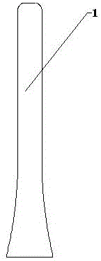
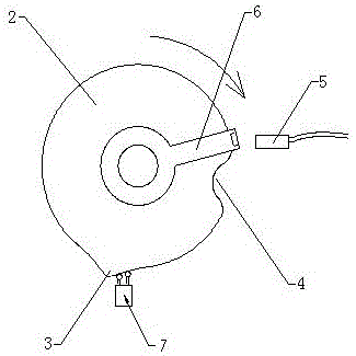
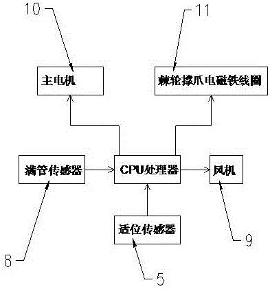
[0042] Examples such as figure 1 , figure 2 , image 3 As shown, a control method for reducing yarn breakage of a spinning frame, the implementation of the device includes a PLC controller and a full pipe sensor 8, a peach plate 2, a position sensor 5, a rotor 7, and a fan 9 arranged on the spinning frame , the main motor 10 and the ratchet support claw, the position sensor 5 and the rotor 7 are arranged on the spinning frame around the peach disk 2, and the full bobbin sensor 8 is arranged at a position equivalent to 90-95% of the total amount of yarn on the bobbin 1. A signal sampler 6 is fixed on the disk 2,

[0043] The peach plate 2 has a peach tip 3 and the lowest end 4 of the peach plate. When the peach tip 3 contacts the rotor 7, the ring plate starts to go down. After rotating until the tip of the peach 3 contacts the rotor 7, the ring plate completes a cycle of spinning steps; when the signal sampler 6 cooperates with the position sensor 5 for induction, the posi...


PUM


Abstract

The invention discloses a control method for reducing yarn broken heads of a spinning frame. The control method comprises a starting step, a small-yarn spinning step, a middle-yarn spinning step, a big-yarn spinning step and a doffing step; in the starting step, a fan is started while a steel collar plate moves up to an initial spinning position, and then the steel collar plate moves up from the initial spinning position till reaching a proper spinning position, and then a primary motor starts to run at low speed, the steel collar plate moves down from the proper spinning position to the initial spinning position and then runs at the low speed and spins, and if the running time is equal to Pd, the middle-yarn spinning step is started; the steel collar plate firstly moves up to the proper spinning position and then moves down to the initial spinning position from the proper spinning position; an air ring is timely opened, the wavelength of the air ring is shortened, the yarn tension is reduced, and the breaking rate of yarns during the small-yarn spinning process is greatly reduced; the steel collar plate motor can be protected; the running time of the steel collar plate motor can be set as 5 seconds after the fan is started; if a sensor is in fault at the initial spinning position, the steel collar plate motor moves up for at most 5 seconds and then stops.

Description

[0001] The present invention is a divisional application of application number 2013100334192, application date January 29, 2013, and title of the invention "control method and device for reducing yarn breakage of spinning frame". technical field [0002] The invention relates to a control method for the spinning process of a spinning frame, which is suitable for the spinning frame, in particular to a control method for reducing yarn breakage of the spinning frame, and belongs to the technical field of textiles. Background technique [0003] In the textile industry, the spinning frame is usually used to spin on the bobbin 1, and reducing the breakage rate of the spinning frame during spinning is the goal that the industry has been pursuing. Traditional equipment still in use in the market, such as FA502, FA503 and A513, etc., mainly use AC contactors to control the spinning process of the entire spinning frame. control. In order to reduce the yarn breakage rate of the spinni...

Claims


Application Information

Patent Timeline
Patent Type & Authority Patents(China)
IPC IPC(8): D01H1/02D01H13/32D01H9/04
CPCD01H1/02D01H13/32
Inventor 马永青赵清滨
Owner 苏州能事达针纺织造有限公司
Why Eureka
Try Eureka