
Wide-dynamic-range device for measuring extinction ratio of star sensor light hood

A large dynamic range, star sensor technology, applied in the direction of measuring devices, instruments, testing optical properties, etc., can solve the problems of low measurement accuracy and slow measurement speed, and achieve the effect of simple experimental operation, convenient operation and large dynamic range

Inactive Publication Date: 2015-04-29
HARBIN INST OF TECH
View PDF10 Cites 8 Cited by
  • Summary
  • Abstract
  • Description
  • Claims
  • Application Information

AI Technical Summary

Problems solved by technology

[0006] The purpose of the present invention is to solve the problems of low measurement accuracy and slow measurement speed in the existing light shield extinction ratio measurement method, and to provide a large dynamic range star sensor light shield extinction ratio measurement device

Method used


Image

  • Wide-dynamic-range device for measuring extinction ratio of star sensor light hood
  • Wide-dynamic-range device for measuring extinction ratio of star sensor light hood
  • Wide-dynamic-range device for measuring extinction ratio of star sensor light hood

Examples


specific Embodiment approach 1

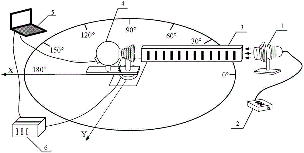
[0020] Specific implementation mode one: combine figure 1 To illustrate this embodiment, the large dynamic range star sensor shading extinction ratio measurement device described in this embodiment includes a radiation emission and shaping subsystem, a mechanical movement and control subsystem, an ambient stray light absorption and suppression subsystem, and radiation data acquisition and processing subsystems;

[0021] The radiation emission and shaping subsystem, the mechanical motion and control subsystem, and the radiation data acquisition and processing subsystem are all located inside the ambient stray light absorption and suppression subsystem;

[0022] The radiation data acquisition and processing subsystem includes an integrating sphere 4 and a computer 5. The integrating sphere 4 is used to measure the energy at the entrance and exit of the light shield, and send the measurement results to the computer 5;

[0023] The radiation emission and shaping subsystem include...

specific Embodiment approach 2

[0034] Specific Embodiment 2: This embodiment is a further limitation of the large dynamic range star sensor shading extinction ratio measurement device described in Embodiment 1. In this embodiment, the inner wall of the ambient stray light absorption and suppression subsystem It is covered with a high absorption rate material coating, and an absorption trap is arranged on the inner wall.

[0035] High-absorbance material coatings and absorption traps can better absorb background stray light.


PUM


Abstract

The invention relates to a wide-dynamic-range device for measuring the extinction ratio of a star sensor light hood, relating to a technology for measuring the extinction ratio of the star sensor light hood, and used for solving the problems of being low in measurement precision and measurement speed in the existing method for measuring the extinction ratio of the light hood. A radiation emitting and shaping sub-system provided by the invention is used for providing a light source for measurement of the extinction ratio; a radiation data acquiring and processing sub-system comprises an integral sphere and a computer; the integral sphere is used for measuring energy at the inlet and the outlet of the light hood and sending a measurement result to the computer; a mechanical motion and control sub-system is used for bearing and driving the light hood, a light hood support structure and the integral sphere to rotate together; and an environmental parasitic light absorbing and inhibiting sub-system is a darkroom and used for absorbing background parasitic light. According to the invention, measurement with the illumination of 10 to 3-1051x can be realized; the integral sphere is used as the receiving device, so that the measurement error is less than 2%; automatic measurement is realized through software integration; the measurement speed is increased; and thus, the wide-dynamic-range device disclosed by the invention is applied to measuring the extinction ratio of the star sensor light hood.

Description

technical field [0001] The invention relates to the measurement technology of the extinction ratio of a star sensor shading cover. Background technique [0002] With the rapid development of aerospace technology, star sensors have been widely used in military and civilian fields such as deep space exploration and ground remote sensing. The star sensor is a low-light photodetector, which is easily affected by background stray light from sunlight, earth atmosphere light, moonlight and other backgrounds when working in orbit. As an important component structure of the star sensor, the light shield undertakes the task of suppressing the main stray light of the star sensor. In order to improve the stray light suppression ability of the hood, the inner wall of the hood is provided with shading buckles at fixed intervals to increase the number of scattering of stray light on the inner wall of the hood, and the inner wall of the hood is oxidized and blackened to reduce the scattere...

Claims


Application Information

Patent Timeline
IPC IPC(8): G01C25/00G01M11/02
CPCG01C25/00G01M11/02
Inventor 汪洪源杜伟峰朱成伟董柏序杨召松
Owner HARBIN INST OF TECH
Learn More