Supercharge Your Innovation With Domain-Expert AI Agents!

A Method to Improve the Working Distance of Distributed Spontaneous Raman Scattering Temperature Sensor

A spontaneous Raman scattering and temperature sensor technology, applied in thermometers, thermometers with physical/chemical changes, instruments, etc., can solve problems such as test distance drop, limit the maximum optical power of injected light, and light source power weakening

Active Publication Date: 2017-12-08
WUHAN WUTOS
View PDF8 Cites 0 Cited by
  • Summary
  • Abstract
  • Description
  • Claims
  • Application Information

AI Technical Summary

Problems solved by technology

However, due to the influence of fiber nonlinear effects, the maximum optical power of the injected light is limited, and the stimulated Raman effect is the most important limiting factor
When the injected optical power increases, the stimulated Raman effect gradually becomes more obvious. When the injected optical power is increased above the stimulated Raman threshold, the injected optical power is rapidly converted into another longer-wavelength Stokes light, resulting in a Rapidly weakens, test distance drops

Method used


Image

  • A Method to Improve the Working Distance of Distributed Spontaneous Raman Scattering Temperature Sensor
  • A Method to Improve the Working Distance of Distributed Spontaneous Raman Scattering Temperature Sensor
  • A Method to Improve the Working Distance of Distributed Spontaneous Raman Scattering Temperature Sensor

Examples


Embodiment Construction

[0024] In order to make the object, technical solution and advantages of the present invention clearer, the present invention will be further described in detail below in conjunction with the accompanying drawings and embodiments. It should be understood that the specific embodiments described here are only used to explain the present invention, not to limit the present invention.

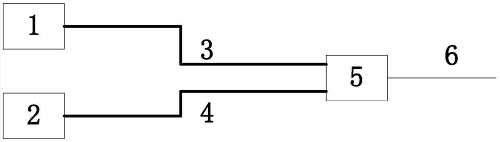
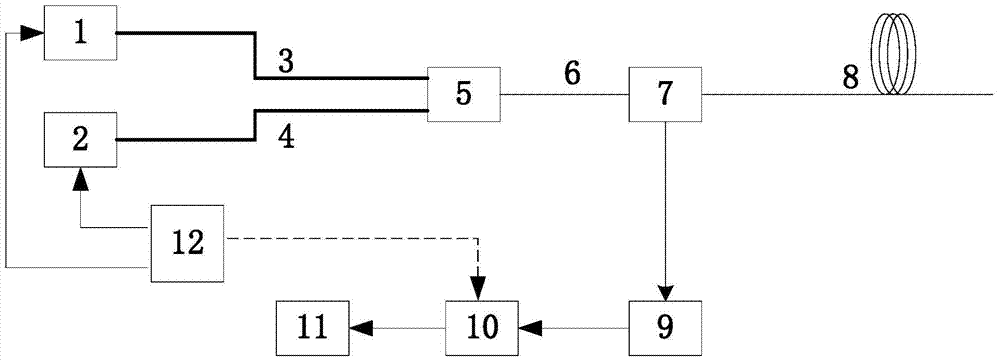
[0025] The whole system can be divided into two parts, such as figure 1 parts shown and figure 2 The next two blocks. figure 1 It shows a design diagram of a light source that improves the working distance of a distributed spontaneous Raman scattering temperature sensor in an embodiment of the present invention. For the convenience of description, only the parts related to the embodiment of the present invention are shown, and the details are as follows:

[0026] The light source part of the whole system includes a first laser (polarization maintaining fiber output) 1, outputting linearly polari...


PUM


Abstract

The invention discloses a method for improving the working distance of a distributed spontaneous Raman scattering temperature sensor. The common output port of the wavelength division multiplexer is output to the sensing optical cable; the polarized light generates reverse Stokes light and anti-Stokes light in the sensing optical cable; the reverse Stokes light and anti-Stokes light The Tox light enters the input end of the avalanche photodiode through the Raman wavelength division multiplexer, and undergoes photoelectric conversion and amplification through it; the amplified signal is synchronously collected by the data acquisition card; the collected data is decoded by the demodulation algorithm unit tune to demodulate the temperature information. The invention can double the maximum optical power that the distributed spontaneous Raman scattering temperature sensor can carry, thereby prolonging the work of the sensor.

Description

technical field [0001] The invention relates to the technical field of distributed spontaneous Raman scattering temperature sensors, in particular to a method and system for improving the working distance of distributed spontaneous Raman scattering temperature sensors. Background technique [0002] Distributed optical fiber temperature sensor is a kind of optical fiber sensing system developed in recent years for real-time measurement of spatial temperature distribution. At present, the sensor is relatively mature, but there are still imperfections. The current development direction of Raman distributed temperature sensors is long distance and high precision. [0003] The working distance of the distributed optical fiber sensor depends on the signal-to-noise ratio. The main factors that determine the signal-to-noise ratio are: the intensity of the injected light source, the APD and circuit noise, and the algorithm. Among them, increasing the injected light intensity is an e...

Claims


Application Information

Patent Timeline
Patent Type & Authority Patents(China)
IPC IPC(8): G01K11/32G01K11/324
Inventor 田铭宋珂印新达
Owner WUHAN WUTOS
Features
  • R&D
  • Intellectual Property
  • Life Sciences
  • Materials
  • Tech Scout
  • Unparalleled Data Quality
  • Higher Quality Content
  • 60% Fewer Hallucinations
Learn More