
A single-fiber multi-directional optical component

An optical component and single-fiber technology, which is applied in the field of single-fiber multi-directional optical components, can solve the problems of reduced coupling efficiency, increased difficulty of coupling process, and high difficulty of automated production, reducing the requirements for installation position accuracy and saving technical costs and time cost, and the effect of avoiding mutual interference of electromagnetic signals

Active Publication Date: 2017-01-25
陈敏
View PDF5 Cites 0 Cited by
  • Summary
  • Abstract
  • Description
  • Claims
  • Application Information

AI Technical Summary

Problems solved by technology

[0003] (1) For the TO package of BK7 glass ball lens with a diameter of 1.5 mm, the laser beam emitted by the laser chip is coupled into the optical fiber, that is, emission coupling, and the coupling efficiency is low, generally less than 15%;
[0004] (2) The laser beam transmitted by the optical fiber is focused on the photosensitive surface of the detector chip, that is, receiving coupling, and the minimum spot diameter reaches 50 microns, which is very unfavorable for coupling;
[0005] (3) The structure of TO packaging is complex, the cost is high, the difficulty of automatic production is high, and the investment cost is also high;
[0006] (4) The position between the chip and the optical element is determined by the size of the TO tube base, TO tube cap, and substrate, and it is difficult to adjust in real time, resulting in a further decrease in coupling efficiency and an increase in the difficulty of the coupling process;
[0007] (5) The pin structure of the TO package makes it difficult for customers to use and automatic welding is difficult;
[0008] In addition, in existing products, optical components with only a single direction are far from meeting industrial needs. For example, optical components that only emit laser beams or only receive laser beams cannot meet the needs of multi-directional transmission and reception of laser beams. great inconvenience

Method used


Image

  • A single-fiber multi-directional optical component
  • A single-fiber multi-directional optical component
  • A single-fiber multi-directional optical component

Examples


Embodiment Construction

[0064] In order to make the technical problems, technical solutions and beneficial effects to be solved by the present invention clearer, the following will describe in detail with reference to the drawings and specific embodiments.

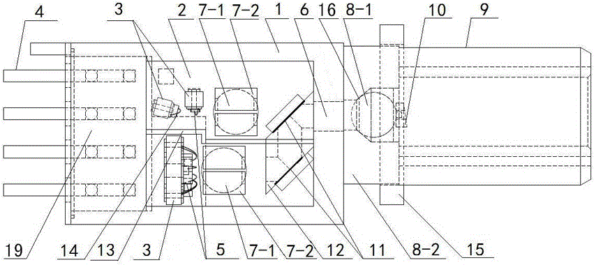
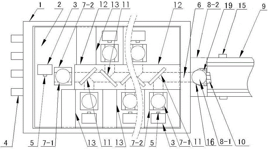
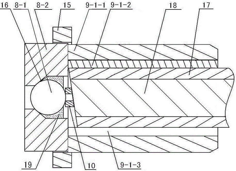
[0065] like figure 1 and Figure 3~7 As shown, embodiment 1: it includes a housing 1, an optical interface component arranged on the housing 1, a main base 2 and a chip support base 3 fixed in the housing 1, respectively arranged on two chips The detector chip and its auxiliary circuit on the support base 3, the laser chip and its auxiliary circuit, and the two chip-end lenses 7-1 correspondingly arranged on the main base 2; one side of the housing 1 has a light-through The hole 6, the optical interface part is aligned with the light hole 6 on the housing 1; the chip support base 3 is welded or glued on the main base 2;

[0066] The two chip-side lenses 7-1 are respectively on the photosensitive surface of the detector chip and the front end of...


PUM


Abstract

The invention discloses a single-fiber multidirection optical component. The multidirection optical module comprises a casing with an aperture in one side, an optical interface component which is arranged outside the casing and is aligned with the aperture, a base fixed in the casing, laser receiving / transmitting devices arranged on the base and chip end lenses, wherein the laser receiving / transmitting devices are detector chips, auxiliary circuits thereof, or laser chips and auxiliary circuits thereof; the optical axes of the chip end lenses and the laser receiving / transmitting devices are coaxially arranged, light diving elements are arranged between the chip end lenses, and the aperture and the optical interface component are coaxially arranged; the optical interface component comprises an optical fiber end lens and an optical fiber sleeve, wherein the optical fiber end lens is positioned between one end of the optical fiber sleeve and the aperture of the casing; the light dividing element comprises light dividing passages and light filtering sheets arranged in the light dividing passages; an electrifying interface is arranged on the base. The multidirection optical component disclosed by the invention has the advantages of high coupling efficiency, high sensitivity, convenience in inserting and plugging, and easiness in automatic manufacturing, and can guide light in multiple directions.

Description

technical field [0001] The invention relates to a single-fiber multi-directional optical component, which belongs to the field of optical elements. Background technique [0002] According to the currently known component structure, the general optical component is to package the chip and the optical element coaxially, that is, the TO package (Transistor-Outline). Fix the TO package and the optical fiber together to make an optical component. The following disadvantages exist in this type of assembly: [0003] (1) For the TO package of BK7 glass ball lens with a diameter of 1.5 mm, the laser beam emitted by the laser chip is coupled into the optical fiber, that is, emission coupling, and the coupling efficiency is low, generally less than 15%; [0004] (2) The laser beam transmitted by the optical fiber is focused on the photosensitive surface of the detector chip, that is, receiving coupling, and the minimum spot diameter reaches 50 microns, which is very unfavorable for c...

Claims


Application Information

Patent Timeline
Patent Type & Authority Patents(China)
IPC IPC(8): G02B6/43G02B6/42
CPCG02B6/4206G02B6/4278G02B6/43
Inventor 陈敏
Owner 陈敏
Learn More