A navigation and positioning method for a substation inspection robot

An inspection robot, navigation and positioning technology, applied in two-dimensional position/channel control and other directions, can solve the problems of heavy ground processing workload, poor path flexibility and high cost, and achieve the effect of simple construction, high precision and low cost

Active Publication Date: 2017-02-08
STATE GRID CORP OF CHINA +3
View PDF4 Cites 0 Cited by
  • Summary
  • Abstract
  • Description
  • Claims
  • Application Information

AI Technical Summary

Problems solved by technology

Under severe weather conditions such as high voltage, ultra-high voltage, rain, snow, fog, etc., it not only endangers the safety of inspection personnel, but also brings certain hidden dangers to the safe operation of the power grid. Opportunities for advance inspection
With the advancement of science and technology, the automation of substation inspections has been greatly improved. Robot inspections through infrared thermal imaging cameras have been widely used. The problem is that the navigation method used by robots will directly affect the inspection results. At present, The navigation methods adopted by substation inspection robots include magnetic trajectory navigation, inertial navigation, GPS navigation and visual navigation. In actual use, magnetic trajectory navigation has been found to have a simple and reliable guiding principle, high navigation positioning accuracy and good repeatability, and is resistant to Strong interference ability and other advantages, but the magnetic trajectory of this navigation method needs to be laid manually, the ground processing workload is large, and the path flexibility is poor. At the same time, the magnetic trajectory navigation method cannot provide real-time feedback on the current precise position of the robot in the substation, which is not conducive to operation; inertia Navigation needs to install a wireless signal transceiver device in the working environment, and the stability is relatively poor; the current accuracy of GPS navigation is low, and its error is within 2-5 meters, which cannot meet the safety requirements of substations; The quantity is relatively abundant, and it has attracted more and more attention in recent years. However, when robots conduct inspections outdoors, they are inevitably affected by changes in light intensity and ground conditions, which have a great impact on the accuracy of robot visual navigation. Visual navigation requires the installation of stereo cameras in the robot's environment, which is expensive
Therefore, the implementation of current navigation methods is relatively complicated, the cost is relatively high, and the stability and accuracy are not very ideal.

Method used


Image

  • A navigation and positioning method for a substation inspection robot
  • A navigation and positioning method for a substation inspection robot
  • A navigation and positioning method for a substation inspection robot

Examples


Embodiment approach 1

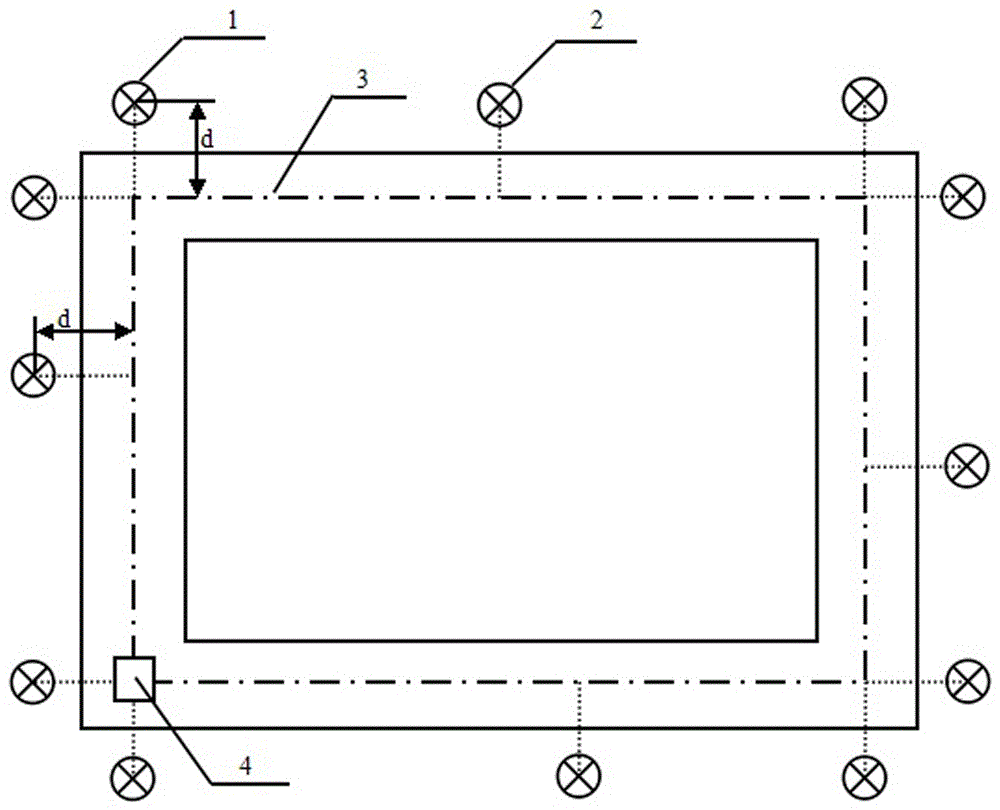
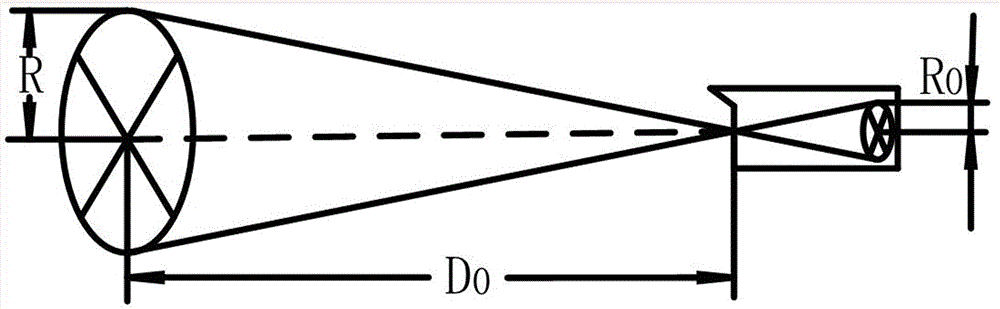
[0024] Implementation mode one: from figure 1 It can be seen that there are four groups of devices to be inspected in this embodiment, and the inspection trajectory of the robot is determined to be a rectangle according to their positions, as shown by the dotted line in the figure. Next, you need to install the tracking navigation light and the positioning navigation light. First, determine the installation location, and extend each side of the rectangular inspection track. The extension length can be set to d. The value of d ensures that when the robot reaches the end of the inspection track, it The imaging of the lamp in the infrared thermal imager preferably takes up 2 / 3 of the image. This position is the installation position of the tracking and navigation light 1. In this embodiment, eight tracking and navigation lights are installed. The position corresponding to each equipment to be inspected on the inspection track is a fixed point. In this embodiment, there are four f...

Embodiment approach 2

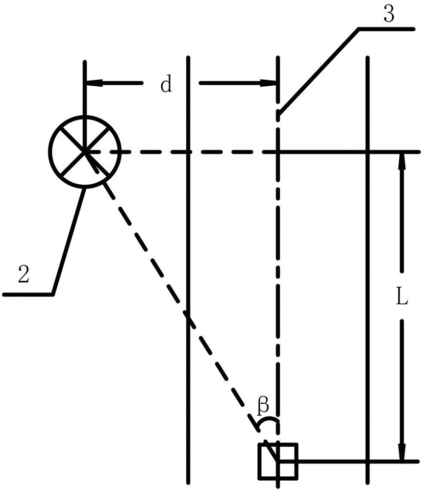
[0048] Embodiment 2: When there is a curved track in the path, the installation method of the tracking navigation light 1 and the positioning navigation light 2 is as follows: Figure 4 , the two straight trajectories transition through a curved trajectory. According to the starting point 4 and the moving direction of the robot marked in the figure, a tracking navigation light 1 is installed at a distance d on the extension line of the rear end of each straight trajectory. The distance d ensures that the tracking The track navigation light 1 is not on the moving track of the robot, and the imaging area of ​​the infrared thermal imaging camera occupies more than 2 / 3 of the imaging area as far as possible. After determining the fixed-point position and quantity according to the equipment to be inspected, locate the distance d beside the straight track of the navigation light installation 0 place, such as Figure 4 As shown in , save the distance D between each fixed point and t...


PUM


Abstract

The invention discloses a navigation positioning method for a tour inspection robot of a transformer substation. The imaging positions of tracking navigation lamps in an infrared thermal imager are detected, so that the moving direction of a trolley is determined, and the aim of tracking is fulfilled; in order to position the robot in a moving process, a cradle head is horizontally rotated until an image of a positioning navigation lamp in the infrared thermal imager is in the center, the distance to the next fixed point is calculated according to the horizontal rotating angle of the cradle head and the moving distance of the trolley is calculated according to the sizes of images of the tracking navigation lamps in the infrared thermal imager, so that the aim of positioning is fulfilled.

Description

technical field [0001] The invention mainly relates to a navigation and positioning method for a substation inspection robot. Background technique [0002] In the past, the power industry generally used manual inspection for the maintenance of outdoor equipment in substations. Under severe weather conditions such as high voltage, ultra-high voltage, rain, snow, fog, etc., it not only endangers the safety of inspection personnel, but also brings certain hidden dangers to the safe operation of the power grid. Opportunity for pre-overhaul. With the advancement of science and technology, the automation of substation inspections has been greatly improved. Robot inspections through infrared thermal imaging cameras have been widely used. The problem is that the navigation method used by robots will directly affect the inspection results. At present, The navigation methods adopted by substation inspection robots include magnetic trajectory navigation, inertial navigation, GPS navi...

Claims


Application Information

Patent Timeline
Patent Type & Authority Patents(China)
IPC IPC(8): G05D1/02
Inventor 樊绍胜贺铁光刘春艳周多思王畅贺亮尹自力刘坚易笃越
Owner STATE GRID CORP OF CHINA
Why Eureka
Try Eureka