
High-speed transmission optical assembly with backlight monitoring function

A high-speed transmission, optical component technology, applied in the field of optical communication, can solve the problem of not being able to monitor the output optical power at any time, and achieve the effect of convenient mold opening and assembly, and simplified structure

Active Publication Date: 2015-04-29
WUHAN HUAGONG GENUINE OPTICS TECH
View PDF6 Cites 16 Cited by
  • Summary
  • Abstract
  • Description
  • Claims
  • Application Information

AI Technical Summary

Problems solved by technology

[0006] The purpose of the present invention is to overcome the defects of the prior art, and provide an optical component with backlight monitoring for high-speed transmission, which can solve the problem that the output optical power cannot be monitored at any time in the prior art, so as to feedback and adjust the threshold current of the laser in real time

Method used


Image

  • High-speed transmission optical assembly with backlight monitoring function
  • High-speed transmission optical assembly with backlight monitoring function
  • High-speed transmission optical assembly with backlight monitoring function

Examples


Embodiment Construction

[0021] The following will clearly and completely describe the technical solutions in the embodiments of the present invention with reference to the accompanying drawings in the embodiments of the present invention. Obviously, the described embodiments are only some, not all, embodiments of the present invention. Based on the embodiments of the present invention, all other embodiments obtained by persons of ordinary skill in the art without making creative efforts belong to the protection scope of the present invention.

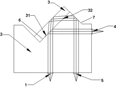
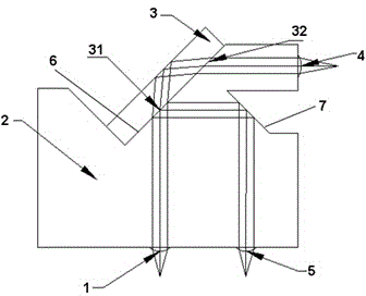
[0022] Such as Figure 1 to Figure 3 An embodiment of the present invention provides an optical component with backlight monitoring for high-speed transmission, including a VCSEL laser, an incident collimating lens 1 , a lens base 2 , a diaphragm 3 , an exit focusing lens 4 and a backlight monitoring lens 5 .

[0023] Such as figure 1 with image 3 , the incident collimating lens 1 and the backlight monitoring lens 5 are disposed on the same side of the lens...


PUM


Abstract

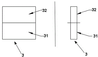
The invention relates to a high-speed transmission optical assembly with the backlight monitoring function. The high-speed transmission optical assembly comprises a VCSEL (Vertical Cavity Surface Emitting Laser), an incidence collimating lens, a lens matrix, a diaphragm, an emergence focusing lens and a backlight monitoring lens, wherein the lens matrix is provided with a first beam turning face and a second beam turning face; the diaphragm is arranged on the first beam turning face; the diaphragm is divided into two half parts; the top half part is an anti-reflection film; the bottom half part is an energy beam splitting film; light emerged from the VCSEL enters the diaphragm through the incidence collimating lens; one part of light is emitted out through the emergence focusing lens after being reflected by the diaphragm; the other part of light enters a diaphragm matrix by refraction of the energy beam splitting film of the diaphragm, enters the second beam turning face after being totally reflected by the other surface of the diaphragm and is emitted out by the backlight monitoring lens after total reflection. The high-speed transmission optical assembly with the backlight monitoring function can effectively solve the problem that a threshold current of the laser cannot be fed back and regulated in real time as power of output light cannot be monitored at any time in the prior art.

Description

technical field [0001] The invention relates to an optical component with backlight monitoring for high-speed transmission, which belongs to the field of optical communication. Background technique [0002] With the development of optical fiber communication technology, the fields of data centers, search engines, and cloud computing have also developed rapidly. Many communication companies use lasers and optical fibers as the main method to solve the transmission of a large amount of audio, video and data on the basis of communication networks. In order to obtain high bandwidth, the light source generally adopts VCSEL laser. [0003] In many applications, the output optical power of a laser is affected by many factors. First, during the use of the laser, changes in the ambient temperature will affect the output of optical power. The main reason is that as the temperature changes, the lasing threshold current of the laser also changes, resulting in a change in the optical ...

Claims


Application Information

Patent Timeline
Patent Type & Authority Applications(China)
IPC IPC(8): H01S5/06H01S5/183
Inventor 杨震王长虹
Owner WUHAN HUAGONG GENUINE OPTICS TECH
Learn More