
Vehicle-mounted charging machine capable of adjusting dead time based on phase-shift full-bridge circuit

A vehicle-mounted charger and phase-shifting full-bridge technology, which is applied in electric vehicles, circuit devices, battery circuit devices, etc., can solve problems such as the difficulty of implementing the lagging arm, and achieve the effects of accurate dead time, precise adjustment, and improved efficiency

Active Publication Date: 2015-04-29
SOUTHEAST UNIV
View PDF4 Cites 10 Cited by
  • Summary
  • Abstract
  • Description
  • Claims
  • Application Information

AI Technical Summary

Problems solved by technology

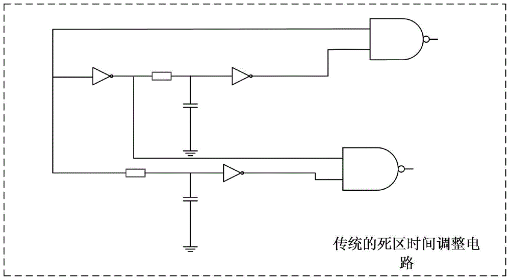
[0004] The purpose of the present invention is to provide a vehicle-mounted charger with adjustable dead time based on the phase-shifting full-bridge circuit structure in view of the defects in the prior art, and solve the lag of the existing phase-shifting full-bridge circuit by dynamically adjusting the dead time It is difficult to realize ZVS (Zero-Voltage Switching) for the lagging arm, so that the lagging arm can also work in the soft switching state under light load, thereby reducing the switching loss of the MOS tube of the full-bridge circuit during operation, and achieving the purpose of improving charging efficiency

Method used


Image

  • Vehicle-mounted charging machine capable of adjusting dead time based on phase-shift full-bridge circuit
  • Vehicle-mounted charging machine capable of adjusting dead time based on phase-shift full-bridge circuit
  • Vehicle-mounted charging machine capable of adjusting dead time based on phase-shift full-bridge circuit

Examples


Embodiment Construction

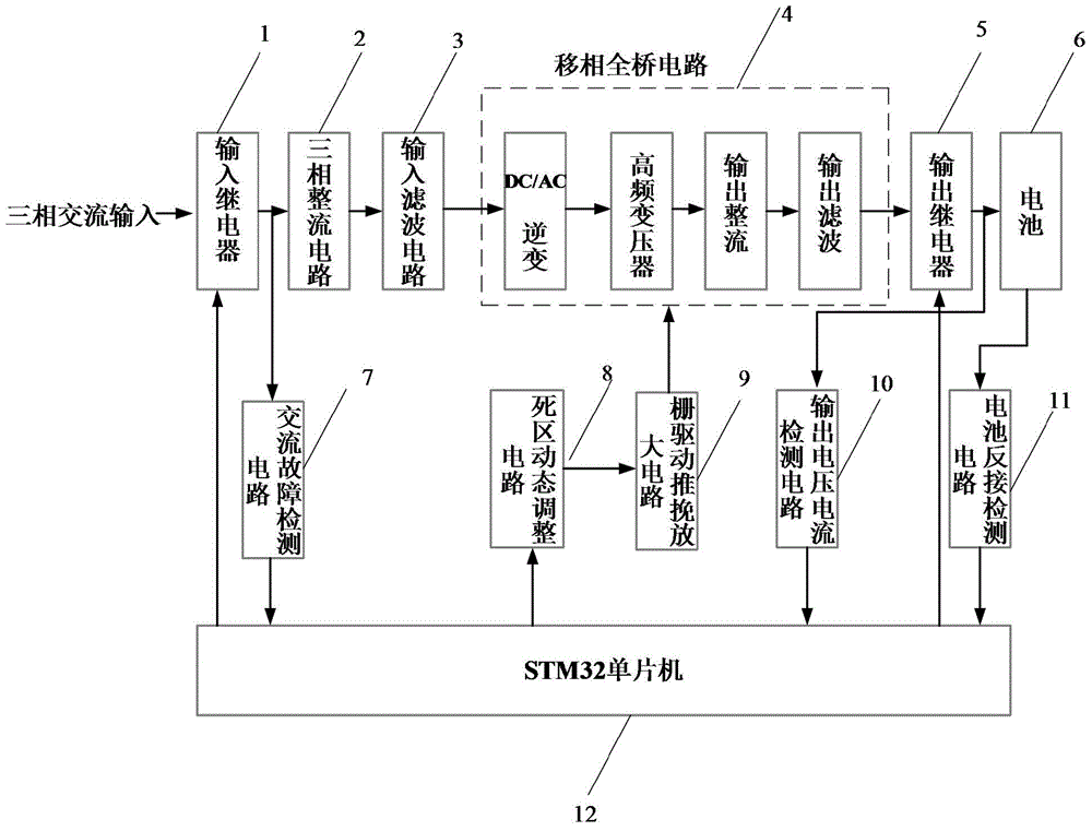
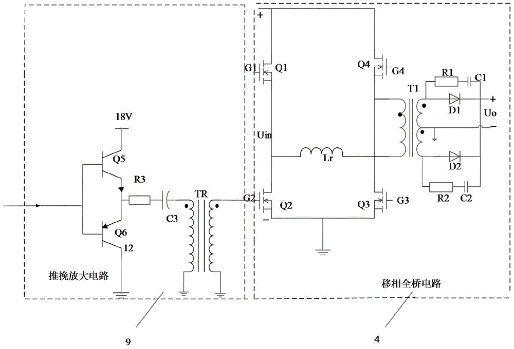
[0026] Such as figure 1, the three-phase AC input is sequentially connected to the input relay 1, the three-phase rectifier circuit 2, the input filter circuit 3, the phase-shifted full-bridge circuit 4 (including DC / AC inverter, high-frequency transformer, output rectifier and output filter), output Relay 5, battery 6, output voltage and current detection circuit 10 are connected between the output terminal of output relay 5 and STM32 single-chip microcomputer 12 (if output relay is not provided, then be connected between phase-shifting full-bridge circuit 4 and STM32 single-chip microcomputer 12), STM32 The single-chip microcomputer 12 outputs four channels of PWM signals and is connected to the dead zone dynamic adjustment circuit 8, and the dead zone dynamic adjustment circuit 8 outputs four channels of four PWM signals with dead zone times, respectively connected to four gate drive push-pull amplifier circuits 9 with the same structure The input terminals of the four grid...


PUM


Abstract

The invention discloses a vehicle-mounted charging machine capable of adjusting the dead time based on a phase-shift full-bridge circuit. The vehicle-mounted charging machine comprises a three-phase rectification circuit, an input filtering circuit, a phase-shift full-bridge circuit and an STM32 single chip microcomputer which are connected in sequence; an output voltage and current detection circuit, a dynamic dead zone adjustment circuit and four gate driving push-pull amplification circuits with the same structures are additionally arranged; the STM32 single chip microcomputer generates four PWM (pulse width modulation) driving signals through a timer according to a sampling value of the output voltage and current detection circuit, and the four PWM driving signals are connected to four input ends of the dynamic dead zone adjustment circuit; the dynamic dead zone adjustment circuit outputs four PWM signals with dead time, and the four PWM signals with the dead time are respectively connected to the input ends of the four gate driving push-pull amplification circuits; the output ends of the four gate driving push-pull amplification circuits respectively control the gates of four switch tubes Q1, Q2, Q3 and Q4 in a phase-shift full-bridge circuit; therefore, dynamic adjustment on the dead time of the phase-shift full-bridge circuit and higher power output are realized, and the working efficiency of the charging machine is greatly improved.

Description

technical field [0001] The invention relates to an on-board charger based on a phase-shifting full-bridge structure, in particular to an on-board charger based on a phase-shifting full-bridge circuit with adjustable dead time. Since the dead time can be dynamically and continuously adjusted, the efficiency within the full load range can be improved . Background technique [0002] With the depletion of traditional energy, the application of new energy, especially electric energy, is becoming a mainstream development trend in the automotive field. However, the popularization of electric vehicles still has many problems to be solved urgently, especially the on-board charger as its charging equipment still has many places to be optimized. For high-power chargers, it is generally based on a phase-shifted full-bridge structure. The gate of the full-bridge circuit is driven by using a single-chip microcomputer chip to generate four pairs of complementary PWM signals. However, th...

Claims


Application Information

Patent Timeline
IPC IPC(8): H02J7/02H02M3/337
CPCH02J7/022H02J2007/10
Inventor 钱钦松张太之娄庆庆祝靖孙伟锋陆生礼时龙兴
Owner SOUTHEAST UNIV
Learn More