Rotating kinetic-energy perpetual-motion generator

A generator and kinetic energy technology, applied to electrical components, electromechanical devices, etc., can solve problems such as low energy conversion rate

Inactive Publication Date: 2015-04-29
何文涛
View PDF0 Cites 0 Cited by
  • Summary
  • Abstract
  • Description
  • Claims
  • Application Information

AI Technical Summary

Problems solved by technology

[0003] The purpose of the present invention is to provide a rotational kinetic energy perpetual generator, which reasonably solves the disadvantages of the low energy conversion rate of the existing power generation technology

Method used


Image

  • Rotating kinetic-energy perpetual-motion generator
  • Rotating kinetic-energy perpetual-motion generator
  • Rotating kinetic-energy perpetual-motion generator

Examples


Embodiment 1

[0099] Embodiment of large rotational kinetic energy perpetual motion generator:

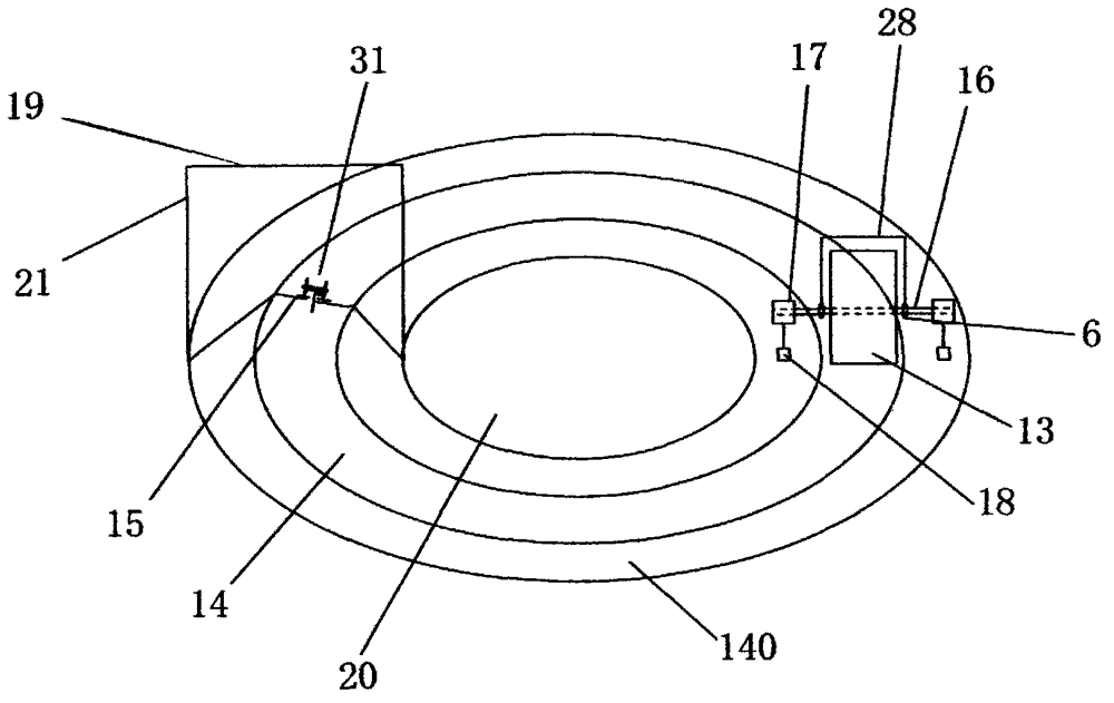
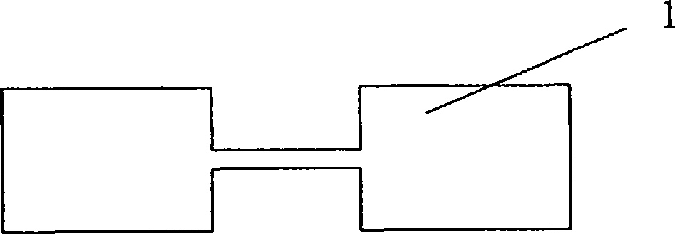
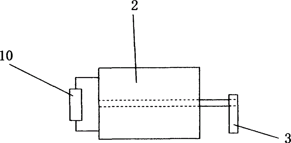
[0100] Such as Figure 2 to Figure 5 The principles shown in Experimental Examples 1 to 5, such as figure 1 , Image 6 , Figure 7 A kind of rotational kinetic energy perpetual motion generator shown is divided into super large, large and small three kinds of rotational kinetic energy perpetual motion generators, such as figure 1 The shown large-scale rotating kinetic energy perpetual generator mainly includes electric traction pull car 31, cylindrical steel column 13, cylindrical steel column fixed shaft 16, generator 17 with the steel column center fixed shaft as the rotating shaft, rolling bearing 6, two The side is provided with components such as the cylinder steel column rolling runway 14 of anti-jump wall 27 and ditch 140. The feature of the large rotational kinetic energy perpetual generator is:

[0101] On a relatively smooth horizontal ring belt with an outer diameter of 1148 me...

Embodiment 2

[0103] Embodiment of the extra-large rotational kinetic energy perpetual generator:

[0104] Such as Image 6 The super large rotary kinetic energy perpetual generator shown in the figure, a single set of super large rotary kinetic energy perpetual generator mainly includes a first-stage cylindrical steel column 131, a central fixed shaft 160 of the first-stage cylindrical steel column, two sets of large rotary Kinetic energy perpetual motion generator equipment and two sides are provided with 0.5M high anti-jump wall 27 and generator 17 shell hanging heavy objects running ditch 140 cylindrical steel column rolling ground runway 14. Between the two ground runways 14, there is a circular runway 141 of a first-level cylindrical steel column, and the runway 141 is set on the raised base 24 of the circular runway of the first-level cylindrical steel column. , the height of the raised base 24 is greater than the diameter of the cylindrical steel column 13 on which the generator is...

Embodiment 3

[0106] Embodiment of small-sized rotational kinetic energy perpetual motion generator:

[0107] Such as Figure 7The small rotary kinetic energy perpetual generator shown in the figure, a single set of small rotary kinetic energy perpetual generator mainly includes a first-stage cylindrical steel column 131, a central fixed shaft 160 of the first-stage cylindrical steel column, a spring 22, and a pulling pulley track 23 for the generator casing , generator housing pull pulley 25, generator housing tension spring running groove 26, traction lever 30, fulcrum hole 33, fulcrum column 34, fulcrum stigma 35, eccentric wheel 36, eccentric wheel drive motor 37, a set and super large rotational kinetic energy A single group of extra-large rotational kinetic energy perpetual generators with the same structure as described in the perpetual generator embodiment, etc. It is characterized in that two ground runways 14 and the raised first-class cylindrical steel column runway 141 of the b...


PUM


Abstract

The invention discloses a rotating kinetic-energy perpetual-motion generator. The rotating kinetic-energy perpetual-motion generator has three types namely a super-large-sized type, a large-sized type and a small-sized type, and mainly comprises an electric traction pulling force vehicle, a cylindrical steel column, a cylindrical steel column fixing shaft, generators, two rolling bearings, a cylindrical steel column rolling runway, and the like, wherein anti-leaping walls and ditches are arranged on two sides of the cylindrical steel column rolling runway. The rotating kinetic-energy perpetual-motion generator is characterized in that a fixing shaft is arranged on the center line of the cylindrical steel column, the rolling bearings are arranged on the fixing shaft, two ends of the fixing shaft are respectively used as rotating shafts of the rotor of one generator, two generators are respectively mounted at two ends of the cylindrical steel column fixing shaft in a suspended manner, a large iron block is suspended on the casing of each electric generator, the cylindrical steel column is driven by smaller force in the runway to perform rolling circular movement, and the fixing shaft drives the generators to rotate so as to generate electricity.

Description

technical field [0001] The present invention relates to a generator, in particular to a rotational kinetic energy perpetual generator. Background technique [0002] Conventional power generation in the prior art is mainly thermal power and water power generation. Due to the large energy loss during the operation of the generator and the fuel combustion process, the energy conversion rate is low. The present invention uses a small power to pull a huge The cylindrical steel column rolls to generate huge rolling kinetic energy, which is then converted into electrical energy, and the obtained electrical energy is much greater than the energy consumed by pulling the cylindrical steel column. After the pulling power is converted into electric energy, a small part of it is converted into the pulling power of the cylindrical steel column to form a perpetual generator. Contents of the invention [0003] The object of the present invention is to provide a rotational kinetic energy ...

Claims


Application Information

Patent Timeline
Patent Type & Authority Applications(China)
IPC IPC(8): H02K53/00
CPCH02K53/00
Inventor 何文涛
Owner 何文涛
Why Eureka
Try Eureka