A zero-crossing detection circuit for inductor current in a power switch chip
A technology of power switch chip and zero-crossing detection circuit, which is applied in the direction of measuring current/voltage, output power conversion device, measuring device, etc., and can solve the problems of requiring device cost and increasing PCB board area, etc.
- Summary
- Abstract
- Description
- Claims
- Application Information
AI Technical Summary
Problems solved by technology
Method used
Image

Examples
Embodiment Construction
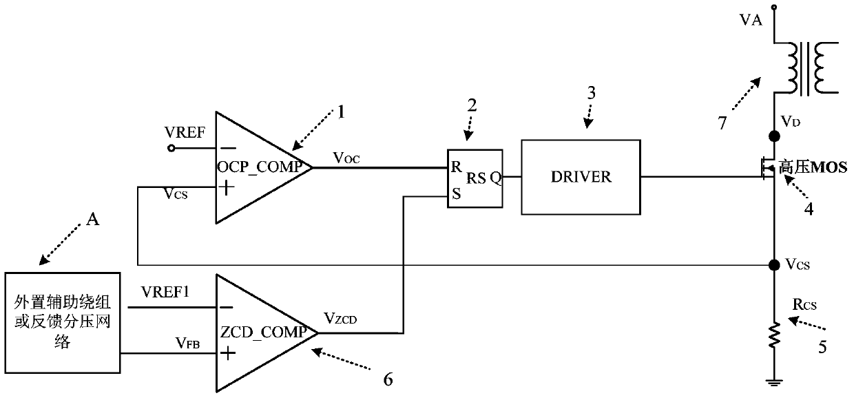
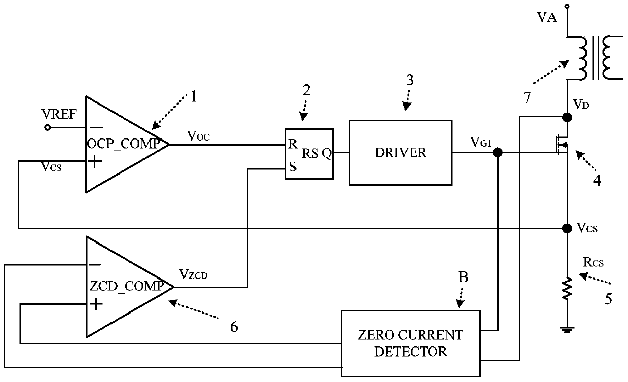
[0020] The specific implementation manners of the present invention will be described in detail below in conjunction with the accompanying drawings. figure 1 It is the zero-crossing detection circuit of the inductor current in the existing power switch chip, figure 2 It is the zero-crossing detection circuit of the inductor current in the power switch chip of the present invention, and the zero-crossing comparison module B is added to replace the external auxiliary winding or feedback voltage divider network A in the prior art, so as to control the opening of the power switch tube 4, that is, the detection transformer The zero-crossing control of the secondary inductor current of 7 is turned on. Therefore, the functions of the first comparator 1, the RS flip-flop 2, the driver stage 3 and the sampling resistor 5 are the same as those of the prior art, and will not be repeated here.
[0021] The first input terminal of the zero-crossing detection module B is connected to the d...
PUM
 Abstract
Description
Claims
Application Information
 - R&D
- Intellectual Property
- Life Sciences
- Materials
- Tech Scout
- Unparalleled Data Quality
- Higher Quality Content
- 60% Fewer Hallucinations
Browse by: Latest US Patents, China's latest patents, Technical Efficacy Thesaurus, Application Domain, Technology Topic, Popular Technical Reports.
© 2025 PatSnap. All rights reserved.Legal|Privacy policy|Modern Slavery Act Transparency Statement|Sitemap|About US| Contact US: help@patsnap.com