Novel three-frequency-band three-dimensional patch antenna

A patch antenna and frequency band technology, which is applied to the antenna, the device that enables the antenna to work in different bands at the same time, and the structural form of the radiation element, etc., can solve the problems of large three-dimensional space, large antenna size, and unfavorable miniaturization of the antenna.

Inactive Publication Date: 2015-07-29
HANGZHOU CENTURY CO LTD
View PDF5 Cites 1 Cited by
  • Summary
  • Abstract
  • Description
  • Claims
  • Application Information

AI Technical Summary

Problems solved by technology

[0003] The radiating body of the traditional patch antenna is usually on the rectangular patch through certain techniques (such as slotting, adding new resonance branches, using high-order resonance, etc.) to increase the resonant frequency band of the antenna and realize the multi-frequency of the antenna, but The introduction of these technologies increases the size of the antenna and occupies a large three-dimensional space, which is not conducive to the miniaturization of the antenna.

Method used


Image

  • Novel three-frequency-band three-dimensional patch antenna
  • Novel three-frequency-band three-dimensional patch antenna

Examples


Embodiment Construction

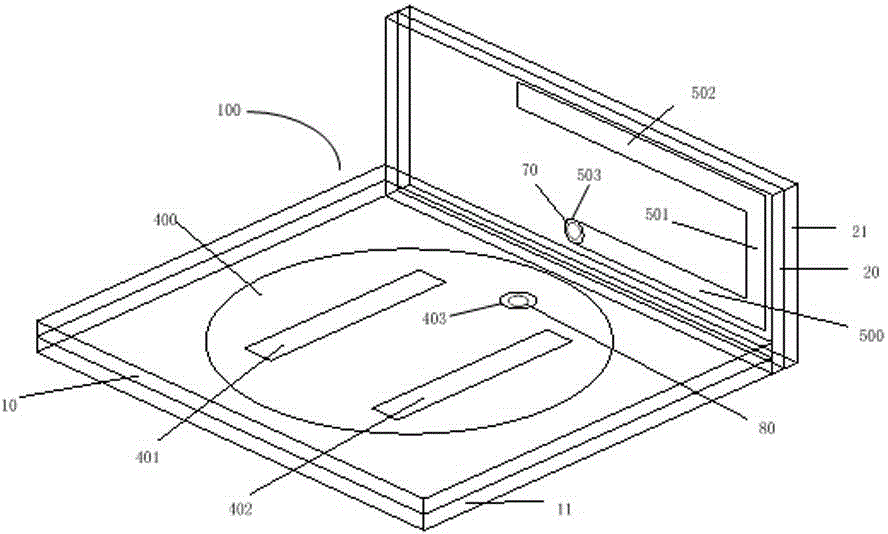
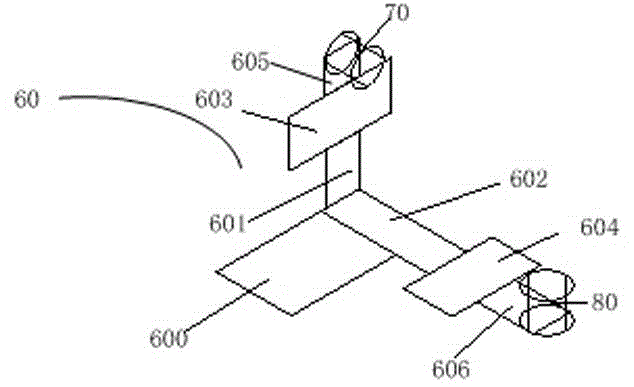
[0016] Refer to attached picture. The three-band three-dimensional patch antenna 100 provided by the present invention includes a first substrate upper layer 10, a first substrate lower layer 11, a second substrate upper layer 20, a second substrate lower layer 21, a first antenna 40 for radiating electromagnetic waves, and a first antenna 40 for radiating electromagnetic waves. The second antenna 50 for electromagnetic waves, the first feed point 403 , the second feed point 501 and the power divider 60 .

[0017] The first substrate is a rectangular non-metal plate composed of two layers of FR4 (glass fiber epoxy resin) media, including the first substrate upper layer 10 and the first substrate lower layer 11, and the second substrate is also a rectangular non-metallic plate composed of two layers of FR4 media. The metal plate includes a second upper substrate layer 20 and a second lower substrate layer 21 . The ground layer is a rectangular printed layer attached to the sur...


PUM


Abstract

The invention provides a novel three-frequency-band three-dimensional patch antenna. The novel three-frequency-band three-dimensional patch antenna comprises a dielectric substrate which is formed by two layers of dielectric substrates, an antenna radiation main body and a power divider; the antenna radiation main body which is arranged on the surface of the dielectric substrate is a printed circuit on an upper surface of the upper layer of a dielectric slab; the power divider is arranged between the two layers of dielectric slabs; a feeding point of the antenna radiation main body is connected with the power divider through a via hole in the upper layer dielectric slab of the two layers of dielectric slabs; the dielectric substrate is connected by the first substrate which is unfolded on a first side and a second substrate which is unfolded on the second side to form into a three-dimensional shape having space angles. According to the novel three-frequency-band three-dimensional patch antenna, a first antenna and a second antenna are printed on the circuit board, a certain space angle is formed between the two substrates, and accordingly space is saved, the feeding point is led out through microstrip line to be used for being integrated on a plate with other circuit boards, and integration is achieved.

Description

technical field [0001] The invention relates to an antenna, in particular to a three-band three-dimensional patch antenna. Background technique [0002] With the rapid development of modern wireless communication technology, mobile products have become the mainstream of technology products at this stage, including mobile phones, notebook computers, routers, etc. These products usually work in multiple frequency bands (such as GSM 900MHz, WLAN 2.45GHz, WiMAX and WLAN 5.8GHz, etc.), which requires that the corresponding antennas can also work in multiple frequency bands. [0003] The radiating body of the traditional patch antenna is usually on the rectangular patch through certain techniques (such as slotting, adding new resonance branches, using high-order resonance, etc.) to increase the resonant frequency band of the antenna and realize the multi-frequency of the antenna, but The introduction of these technologies increases the size of the antenna and occupies a large thr...

Claims


Application Information

Patent Timeline
Patent Type & Authority Applications(China)
IPC IPC(8): H01Q5/10H01Q13/08H01Q1/38
Inventor 商巍陈敏华贾宇周琳
Owner HANGZHOU CENTURY CO LTD
Why Eureka
Try Eureka