FET-based rectifier circuit

A technology of rectifier circuit and field effect tube, which is applied in the field of rectifier circuit based on field effect tube, can solve the problems of large space occupation, large power consumption and serious heat generation of diode rectifier circuit

Pending Publication Date: 2019-11-19
深圳市泛海数据科技有限公司
View PDF0 Cites 0 Cited by
  • Summary
  • Abstract
  • Description
  • Claims
  • Application Information

AI Technical Summary

Problems solved by technology

[0004] This application provides a rectifier circuit based on field effect transistors, which solves the technical probl...

Method used


Image

  • FET-based rectifier circuit
  • FET-based rectifier circuit
  • FET-based rectifier circuit

Examples


Embodiment 1

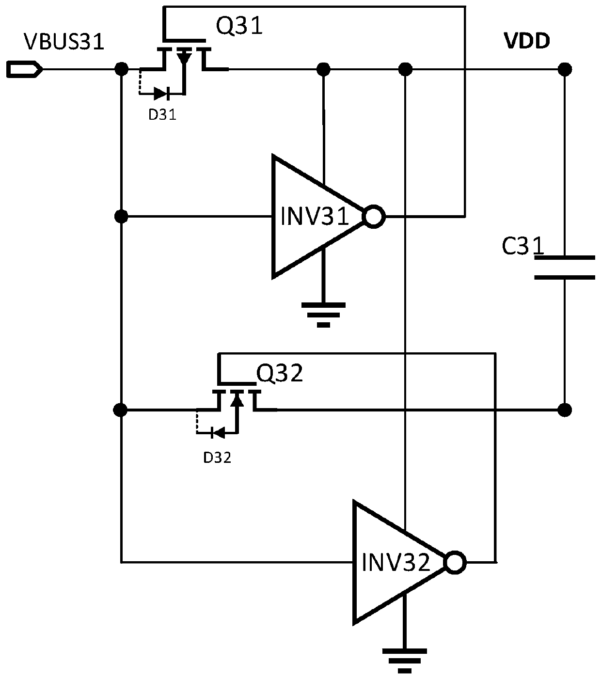
[0075] Please refer to image 3 , is a schematic circuit diagram of a voltage rectification unit in an embodiment. The field effect transistor-based rectification circuit disclosed in this application includes one or more voltage rectification units, and each voltage rectification unit includes a first inverter INV31, a second inverter The phase device INV32, the first field effect transistor Q31 and the second field effect transistor Q32 are used to rectify the input voltage signal VBUS31. The first pole of the first field effect transistor Q31 is connected to the input terminal of the first inverter INV31 as the input terminal of the voltage rectification unit for inputting the rectified voltage signal VBUS31. The second pole of the first field effect transistor Q31 is connected to the voltage input end of the first inverter INV31 as the first output end of the voltage rectification unit. The control electrode of the first field effect transistor Q31 is connected to the out...

Embodiment 2

[0083] Please refer to Figure 7 , which is a schematic circuit diagram of a voltage rectification unit in another embodiment, and the present application also discloses a rectification circuit based on a field effect transistor, including one or more voltage rectification units, each voltage rectification unit including a load capacitor C71, a first An inverter INV71, a second inverter INV72, a first rectification module and a second rectification module are used to rectify the input voltage signal. The first rectification module includes a control terminal, an input terminal and an output terminal, for outputting a voltage signal at the input terminal of the first rectification module to an output terminal of the first rectification module when a negative voltage signal is input to the control terminal of the first rectification module. It is also used for not outputting the voltage signal at the input end of the first rectification module to the output end of the first rect...


PUM


Abstract

The application discloses a FET-based rectifier circuit which includes an energy storage load and a plurality of voltage rectification units. Each voltage rectification unit includes a first output end and a second output end. The energy storage load is connected in series between the first output end and the second output end of each voltage rectification unit and is configured to be charged anddischarged. Each voltage rectification unit includes a first inverter, a second inverter, a first field-effect transistor, and a second field-effect transistor, and is configured to rectify an input voltage signal. Because the field-effect transistors rectify the input voltage signal instead of rectifier diodes, the electric power consumed by the rectifier circuit is reduced, the heat generation is reduced, and integration can be achieved to reduce the occupied area of the circuit.

Description

technical field [0001] This application relates to the technical field of voltage shaping and filtering, and specifically relates to a rectifier circuit based on a field effect transistor. Background technique [0002] The commonly used rectification circuit in the prior art uses a rectification diode as a rectification element to build a rectification circuit to rectify AC into DC to achieve polarity independence. Since the tube voltage of the diode itself is relatively high (usually the forward conduction voltage drop of the rectifier diode is 0.5-1.5V, and the conduction voltage drop of the diode in the full-bridge rectifier bridge circuit is 1.4-3V), the rectifier bridge built directly with diodes The electric power consumption of the circuit is relatively large under the operation of high current, and the heat generation is also relatively serious (need to configure cooling devices separately, such as heat sinks and fans, etc.), it occupies a large area on the PCB, and ...

Claims


Application Information

Patent Timeline
IPC IPC(8): H02M7/219
CPCH02M7/219
Inventor 马彪李芳
Owner 深圳市泛海数据科技有限公司
Why Eureka
Try Eureka