Engine hole type oil nozzle single-hole extruding and grinding device and use method

A technology for grinding devices and fuel injectors, which is applied in the direction of measuring devices, testing of mechanical components, testing of machine/structural components, etc. It can solve the problem of inability to repair and evaluate the shape and structure of a single nozzle hole, and the inability to uniform flow rate of a single nozzle hole Performance testing and other issues to achieve the effects of reducing fuel consumption and harmful gas emissions, improving combustion and emission processes, and improving mixing quality

Active Publication Date: 2015-05-06
CHINA FAW LIMITED WUXI FUEL INJECTIONEQUIP RES INST +1
View PDF8 Cites 11 Cited by
  • Summary
  • Abstract
  • Description
  • Claims
  • Application Information

AI Technical Summary

Problems solved by technology

If the nozzle flow coefficient is not up to the standard, repeated liquid extrusion and grinding will have great randomness in the shaping of the nozzle holes. At the same time, it is impossible to repair the shape and structure of a single nozzle hole. When the requirements are high and the nozzles cannot meet the requirements, scrap and reprocess new nozzles. When the nozzle flow detection test bench is used to detect the flow of the nozzle, the flow rate of a single nozzle hole and the flow rate between each nozzle hole cannot be measured. The flow uniformity of the test and evaluation has great limitations

Method used


Image

  • Engine hole type oil nozzle single-hole extruding and grinding device and use method
  • Engine hole type oil nozzle single-hole extruding and grinding device and use method
  • Engine hole type oil nozzle single-hole extruding and grinding device and use method

Examples


Embodiment Construction

[0037] The present invention will be further described in detail below in conjunction with the accompanying drawings and specific preferred embodiments.

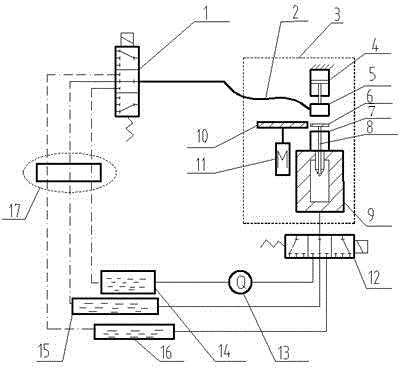
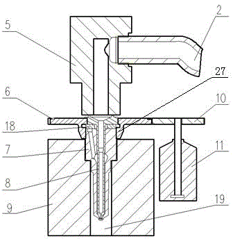
[0038] The fuel injector body 7 to be ground in the present invention is a prior art, and the fuel injector body 7 is fixed on the nozzle seat 9 with an emptying pipeline 19 inside. Such as Image 6 with Figure 7As shown, the bottom of the injector body 7 is provided with several injector holes 26 . The spray holes 26 of the fuel injectors may be arranged in a single layer uniformly distributed along the axial direction, or distributed in a single layer but with different inclination angles, or distributed in multiple layers. The single-hole squeezing and grinding device of the engine hole type fuel injector of the present invention is applicable to all above-mentioned arrangement modes of the spray hole 26 of the fuel injector.

[0039] Such as figure 1 As shown, a single-hole squeezing and grinding device for an engin...


PUM


Abstract

The invention discloses an engine hole type oil nozzle single-hole extruding and grinding device and a use method. The engine hole type oil nozzle single-hole extruding and grinding device comprises an oil nozzle seat, an oil nozzle body and a shaft needle single-hole circulation rod sleeve which is arranged in the oil nozzle body and can rotate. A ball head at the bottom of the shaft needle single-hole circulation rod sleeve is provided with a rod sleeve spraying hole which can be communicated with any oil nozzle spraying hole after rotating, a sealing face is arranged between the ball head and the oil nozzle body, and the bottom of the oil nozzle seat is further connected with at least one working liquid box through a discharging electromagnetic valve. By means of the structure and the method, the shaft needle single-hole circulation rod sleeve can rotate and drive the rod sleeve spraying hole to rotate so that the rod sleeve spraying hole can be communicated with any oil nozzle spraying hole, and flow or spraying characteristic detection or uniformity evaluation or repairing operation can be conducted on any independent oil nozzle spraying hole. Due to the multiple working liquid boxes, the discharging electromagnetic valve and the like, fast switching of flow detection or grinding or cleaning operation can be achieved by directly controlling the actions of feeding and discharging electromagnetic valves.

Description

technical field [0001] The invention relates to an engine fuel injector nozzle processing device and a using method thereof, in particular to a single-hole extrusion grinding device and a using method of an engine hole type fuel injector nozzle. Background technique [0002] Energy crisis and environmental pollution are two major problems facing the world today, and the engine consumes a lot of fuel energy and emits a lot of harmful gas pollutants, which is the main producer of energy and environmental problems, so how to improve the fuel of the engine Utilization efficiency and reduction of harmful emissions are of great significance. [0003] In the engine, the injection effect of the fuel injection system directly affects the utilization rate of fuel and the emission of harmful gases, and the fuel injector is one of the important components in the fuel system. have a very important impact. With the wide application of common rail technology, fuel injectors are also grad...

Claims


Application Information

Patent Timeline
Patent Type & Authority Applications(China)
IPC IPC(8): B23P6/00B23P15/00B23P23/02G01M13/00
CPCB23P6/00B23P15/00B23P23/02G01M13/00
Inventor 郑金保缪雪龙赵智博王对对夏少华居钰生
Owner CHINA FAW LIMITED WUXI FUEL INJECTIONEQUIP RES INST
Why Eureka
Try Eureka