Low Back Pressure Rotary Compressors

A rotary compressor, low back pressure technology, applied in the field of compressors, can solve the problems of sliding vane and piston collision, motor tripping, compressor performance deterioration, etc., to achieve the effect of ensuring close sealing and good compressor performance

Active Publication Date: 2016-06-29
GUANGDONG MEIZHI COMPRESSOR
View PDF6 Cites 0 Cited by
  • Summary
  • Abstract
  • Description
  • Claims
  • Application Information

AI Technical Summary

Problems solved by technology

If the structural volume design of the vane cavity is unreasonable, it may occur that when the maximum pressure of the vane cavity is too large, the power consumption of the compressor will increase, and even the abnormal current will cause the motor to trip and stop. If the minimum pressure of the cavity is too small, the close contact between the tip of the sliding vane and the outer diameter of the piston cannot be ensured, resulting in abnormal sound and abnormal wear caused by the collision between the sliding vane and the piston, and leakage leading to performance deterioration of the compressor

Method used


Image

  • Low Back Pressure Rotary Compressors
  • Low Back Pressure Rotary Compressors
  • Low Back Pressure Rotary Compressors

Examples


Embodiment 1

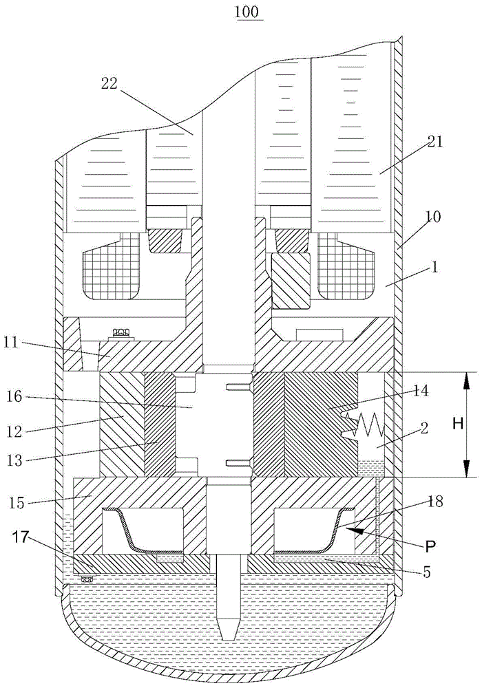
[0087] Such as figure 1 As shown, the low back pressure rotary compressor 100 according to the embodiment of the present invention includes: a casing 10, a motor and a compression mechanism. The housing 10 defines an inner space 1 communicating with the suction port. The motor is located on the top of the inner space 1. The motor is composed of a stator 21 and a rotor 22, wherein the rotor 22 is connected to the crankshaft 16 to drive the crankshaft 16 to rotate.

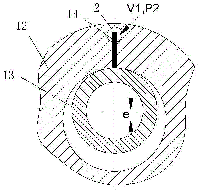
[0088] The compression mechanism includes: a cylinder 12 , a piston 13 and a sliding plate 14 arranged in the cylinder 12 , a crankshaft 16 for driving the piston 13 to rotate eccentrically, and a main bearing 11 and an auxiliary bearing 15 supporting the crankshaft 16 .

[0089] During the operation of the compressor, the sliding vane 14 reciprocates along the sliding vane groove 4 provided on the cylinder 12 , and the tip of the sliding vane 14 closely fits the outer diameter of the piston 13 to form a compression...

Embodiment 2

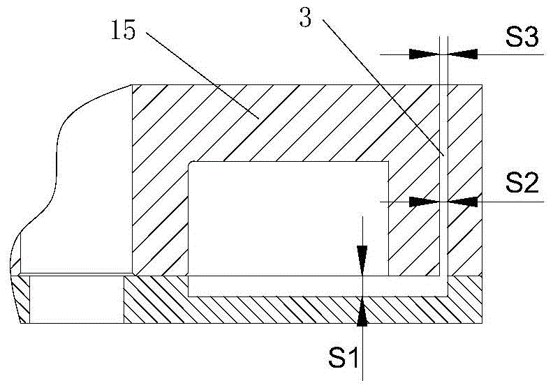
[0099] Such as Figure 5 As shown, in this embodiment, the oil separator 18 of the low back pressure rotary compressor 100 is disposed outside the casing 10 , and the oil separator 18 communicates with the exhaust hole 6 . The oil pool 5 is arranged at the bottom of the oil separator 18, the inlet of the slide vane oil supply path 3 communicates with the oil pool 5 arranged in the oil separator 18, and the slide vane oil supply path 3 is connected to the oil pool 5 and the slide vane cavity 2 The oil supply pipe, the outlet of the slide vane oil supply path 3 , that is, the oil supply hole of the slide vane cavity 2 is located in the middle of the slide vane cavity 2 .

[0100] Among them, the distance between the oil supply hole and the bottom of the vane chamber 2 is d, and the height of the vane chamber 2 is H, and there are:

[0101] 0

[0102] The rest are the same as in Embodiment 1 and will not be repeated here.

Embodiment 3

[0104] Such as Figure 7 and Figure 9 As shown, in this embodiment, the difference from Embodiment 1 and Embodiment 2 is that the compression mechanism has two cylinders up and down, that is, the cylinder assembly includes an upper cylinder 12a, a lower cylinder 12b and a middle partition, and the middle partition is arranged on the upper Between the cylinder 12a and the lower cylinder 12b, correspondingly, the slide chamber 2 also includes the upper slide chamber 2a and the lower slide chamber 2b, and the slide chamber 2a of the upper cylinder 12a and the slide chamber 2b of the lower cylinder 12b are connected with the oil pool respectively. In addition, the oil supply path 3 of the slide chamber also includes an upper oil supply path 3a and a lower oil supply path 3b,  ….

[0105] That is to say, in this embodiment, the upper cylinder 12a and the lower cylinder 12b are respectively analyzed as independent cylinders, the volume V of the slide cavity of the two cylinders, t...


PUM


Abstract

A disclosed low-backpressure rotary type compressor comprises a housing, a compression mechanism, an oil separator for performing oil-gas separation on a refrigerant discharged from a cylinder, and an oil pool for holing lubricating oil separated from the oil separator; the compression mechanism comprises a cylinder assembly, a piston, a slide sheet, a main bearing and an auxiliary bearing; the cylinder possesses a slide-sheet chamber, the slide-sheet chamber is provided with an oil supply hole, and when the slide sheet makes reciprocated motions, the tail end of the slide sheet stretches into or out of the slide-sheet chamber so as to enable the internal capacity of the slide-sheet chamber to be varied between a maximum capacity V2 and a minimum capacity V1; and the oil pool is communicated with the oil supply hole via a slide-sheet oil supply path, and the ratio of the maximum capacity V2 and the minimum capacity V1 satisfies the following relationship: 35%<=V1 / V2<=85%. According to the low-backpressure rotary type compressor, the pressure fluctuation of the slide-sheet chamber is not too large or too small, clinging seal between the slide sheet and the piston is guaranteed, and when the stress demand of the slide sheet is relatively well satisfied, relatively good compressor performances are realized.

Description

technical field [0001] The invention relates to the field of compressors, in particular to a low back pressure rotary compressor. Background technique [0002] In the low back pressure rotary compressor, due to the low-pressure suction pressure environment inside the shell, the gas force acting on the tail end of the slide vane is not enough to ensure the close contact between the tip of the slide vane and the outer diameter of the piston. Therefore, it is necessary to place the tail end of the slide vane The design of the region forms a sliding vane cavity that is sealed and separated from the inner diameter of the housing, and provides a relatively high-pressure environment for the sliding vane cavity to ensure that the tip of the sliding vane is in close contact with the outer diameter of the piston. Moreover, since the vane cavity needs to be sealed and separated from the inside of the housing, the oil pool inside the housing cannot be used to achieve lubrication. Theref...

Claims


Application Information

Patent Timeline
Patent Type & Authority Patents(China)
IPC IPC(8): F04C29/00
CPCF04C18/356F04C29/02F04C29/026
Inventor 高斌喻继江郭宏
Owner GUANGDONG MEIZHI COMPRESSOR
Why Eureka
Try Eureka