Magneto-Rheological Shock Absorber with Double-tube Structure Based on Flow Mode

A magneto-rheological shock absorber, flow mode technology, applied in the direction of shock absorber, shock absorber, spring/shock absorber, etc. The application range of the vibrator and other problems are solved to achieve the effect of large working stroke, compact structure and improved working stroke

Active Publication Date: 2016-08-24
CHONGQING MATERIALS RES INST
View PDF6 Cites 10 Cited by
  • Summary
  • Abstract
  • Description
  • Claims
  • Application Information

AI Technical Summary

Problems solved by technology

[0003] In the current magnetorheological shock absorber, the excitation coil is mainly wound on the piston, and the excitation coil wire is led out of the shock absorber through the deep hole processing of the piston rod. During the movement of the piston, a high temperature is generated due to friction, and the coil is energized at the same time. It will also generate heat itself, which will easily cause the heat accumulation of the coil, resulting in the excessive concentration of heat at the piston and the dilution of the magneto-rheological fluid, resulting in a decrease in the damping performance of the shock absorber; as a single-rod shock absorber, it is necessary to set the volume compensation of the piston rod inside mechanism, often the compensation mechanism and the piston are in the same cavity, which seriously limits the working stroke of the shock absorber and restricts the application range of the shock absorber

Method used


Image

  • Magneto-Rheological Shock Absorber with Double-tube Structure Based on Flow Mode

Examples


Embodiment Construction

[0018] In order to make the purpose, technical scheme and advantages of the present invention clearer, detailed implementation and specific operation process are provided, and the present invention will be further described in detail below in conjunction with the accompanying drawings:

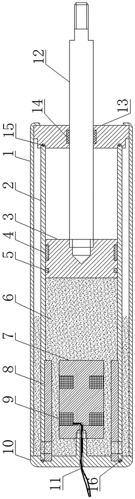
[0019] see figure 1 , a magneto-rheological shock absorber with double cylinder structure based on flow mode, including an outer cylinder 1 and an inner cylinder 2 installed in the outer cylinder 1, and a gap is left between the outer cylinder 1 and the inner cylinder 2 The upper and lower ends of the outer cylinder 1 and the inner cylinder 2 are sealed by the end cover 13 and the base 10 respectively. Both the base 10 and the end cover 13 are provided with a bayonet for clamping the inner cylinder 2, the upper end of the inner cylinder 2 is fixed by the bayonet provided on the end cover 13, and the lower end of the inner cylinder 2 passes through The bayonet provided on the base 10 is fixed,...


PUM


Abstract

The invention relates to a double-barrel-structure magneto-rheological shock absorber based on a flow mode. The double-barrel-structure magneto-rheological shock absorber comprises an outer cylinder barrel and an inner cylinder barrel which is installed in the outer cylinder barrel, wherein a gap is formed between the outer cylinder barrel and the inner cylinder barrel, the upper end and the lower end of each of the outer cylinder barrel and the inner cylinder barrel are respectively sealed to a base through an end cover, through holes are formed in the circumferential wall of the lower end of the inner cylinder barrel, an inner cavity of the inner cylinder barrel is communicated with the gap between the inner cylinder barrel and the outer cylinder barrel through the through holes, a piston is arranged in the inner cavity of the inner cylinder barrel, the piston is fixedly connected with a piston rod, one end of the piston rod is fixedly connected with the piston, the other end of the piston rod stretches out of the end cover, a through hole which is used for the piston rod to run through is formed in the end cover, the space between the piston and the base in the inner cavity of the inner cylinder barrel is filled with magneto rheological liquid, a magnetic field adjusting device is fixed on the base, and a conducting wire of the magnetic field adjusting device is led out from a leading-out hole formed in the base. By adopting the double-barrel-structure magneto-rheological shock absorber, the working stroke of the shock absorber is increased, the application range of the shock absorber is enlarged, and the dissipation of the working heat of the shock absorber in long time can be facilitated.

Description

technical field [0001] The invention belongs to the technical field of shock absorbers, and in particular relates to a magneto-rheological shock absorber with double-tube structure based on a flow mode. Background technique [0002] Magnetorheological fluid is an intelligent dispersion material composed of soft magnetic suspension phase, organic suspension medium and additives. Under the action of an external magnetic field, its viscosity can be adjusted continuously, rapidly and reversibly. Through the control of the magnetic field, a continuously adjustable damping force is generated. Vibration control technology based on magnetorheological vibration reduction has been used in automobiles, machinery, construction, aviation and other fields. [0003] In the current magnetorheological shock absorber, the excitation coil is mainly wound on the piston, and the excitation coil wire is led out of the shock absorber through the deep hole processing of the piston rod. During the ...

Claims


Application Information

Patent Timeline
Patent Type & Authority Patents(China)
IPC IPC(8): F16F9/53F16F9/36F16F9/54F16F9/32
CPCF16F9/32F16F9/3257F16F9/36F16F9/535F16F9/54
Inventor 居本祥唐锐张登友杨百炼
Owner CHONGQING MATERIALS RES INST
Why Eureka
Try Eureka