Integral abutment bridge structure based on composite flexible piles and construction method thereof

An integral abutment and construction method technology, which is applied in the direction of foundation structure engineering, bridges, bridge parts, etc., can solve the problems of high horizontal rigidity of ordinary concrete piles, concrete cracking, fracture failure of pile foundation structure sections, etc., and achieve high temperature absorption Performance, improve the mechanical performance, the effect of reasonable design

Inactive Publication Date: 2015-05-13
FUZHOU UNIV
View PDF5 Cites 2 Cited by
  • Summary
  • Abstract
  • Description
  • Claims
  • Application Information

AI Technical Summary

Problems solved by technology

[0004] The object of the present invention is to provide a kind of integrated abutment bridge structure and its construction method based on composite flexible piles, to eliminate the large horizontal rigidity of ordinary concrete piles, the poor longitudinal deformation capacity of the bridge, and the small design value of ordinary concrete tensile strength. Concrete cracking is easy to occur under external influence, and even eventually leads to the failure of pile foundation structure section fracture

Method used


Image

  • Integral abutment bridge structure based on composite flexible piles and construction method thereof
  • Integral abutment bridge structure based on composite flexible piles and construction method thereof
  • Integral abutment bridge structure based on composite flexible piles and construction method thereof

Examples


Embodiment Construction

[0030] In order to make the above-mentioned features and advantages of the present invention more comprehensible, the following specific embodiments are described in detail with reference to the accompanying drawings, but the present invention is not limited thereto.

[0031] refer to Figure 1 to Figure 8

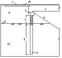
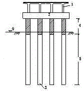
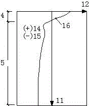
[0032] An integral abutment bridge structure based on composite flexible piles, including an abutment 2 lying along a slope protection 6, the abutment is supported by a number of vertical flexible piles 3 embedded in the slope protection, and the flexible piles are buried by It is composed of the ordinary concrete area 5 in the geology 10 below the surface line 9 and the ultra-high performance fiber concrete composite material area 4 connected thereto, and the space between the abutment and the flexible pile and the bank ground is filled with filling Soil 8, the filling is laid with a board 7, and the end of the board near the abutment is overlapped with the end of the ma...


PUM


Abstract

The invention relates to the field of bridges, in particular to an integral abutment bridge structure based on composite flexible piles and a construction method thereof. The structure comprises an abutment horizontally arranged along a revetment, wherein the abutment is supported by the multiple vertical flexible piles embedded in the revetment, the flexible piles are composed of an ordinary concrete area embedded in the ground under the earth surface line and an ultra-high-performance fiber reinforced concrete composite material area connected to the ordinary concrete area, filling soil is stacked in the spaces between the abutment and the shoreside ground and between the flexible piles and the shoreside ground, approach slabs are laid on the filling soil, and the bear-abutment end of each approach slab is in lap joint with the end of a main beam arranged on the abutment. The structure aims to solve the problem that due to the fact that ordinary concrete piles are high in rigidity and poor in longitudinal-bridge-direction deformability and the tensile strength design value of ordinary concrete is small, concrete cracking can be caused easily under the external influence, or even fracture failure of the section of a pile foundation structure can be caused finally.

Description

technical field [0001] The invention relates to the field of bridges, in particular to an integral abutment bridge structure based on composite flexible piles and a construction method thereof. Background technique [0002] Due to the integral pouring of the abutment and the end of the main girder of the integral abutment bridge, the bridge support and the expansion joint of the bridge are cancelled, thereby saving the maintenance cost of the bridge; improving the driving condition; improving the durability of the bridge . Therefore, the design scheme of the integral abutment bridge has been recognized by engineers at home and abroad. However, since the superstructure and substructure of the integral abutment bridge are poured as a whole, and the telescopic device is cancelled, any slight expansion and contraction deformation of the main girder will affect the stress condition of the substructure. In order to adapt to the deformation of the superstructure, the longitudinal...

Claims


Application Information

Patent Timeline
Patent Type & Authority Applications(China)
IPC IPC(8): E02D5/48E02D5/30E01D19/02
CPCE01D19/02E02D5/30E02D5/48E02D27/12E02D2300/002Y02A30/30
Inventor 庄一舟丘能徐亮陈云赖焕林
Owner FUZHOU UNIV
Why Eureka
Try Eureka