

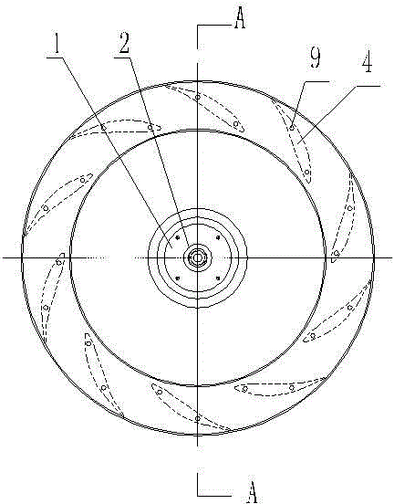
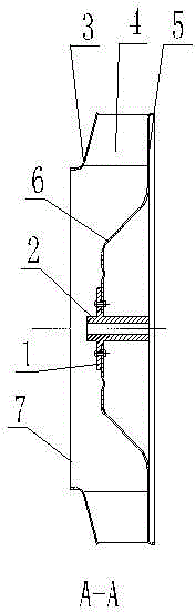
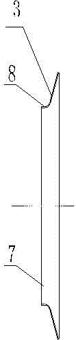
Wing sectional material combination type turbine centrifugal impeller
A combined and centrifugal technology, applied in the direction of non-variable pumps, supporting elements of blades, components of pumping devices for elastic fluids, etc., can solve problems such as high production costs, poor versatility, and complex molds
- Summary
- Abstract
- Description
- Claims
- Application Information
AI Technical Summary
Problems solved by technology
Method used
Image

Examples
Embodiment 1
[0064] Embodiment 1: the making of centrifugal airfoil profile
[0065] Centrifugal airfoil blade profile of the present invention is made into following two big classes:
[0066] 1. Aviation aerodynamic standard airfoil structure profiles
[0067] The document "Method for Manufacturing High-efficiency Energy-saving Fan Impeller Using Airfoil Structure Sections" discloses the cross-sectional structure of standard airfoil structure sections of aviation aerodynamics, including asymmetric airfoils (as attached Figure 6 ), symmetrical airfoil (if attached Figure 7 ), and the airfoil derived from the symmetrical airfoil based on the center arc is also included here (as shown in the attached Figure 8 ), the middle arc can be a single arc or a combination of multiple arcs, it can also be a part of an elliptic curve, or it can be a part of other function curves and their combination;
[0068] 2. Composite airfoil structure profile generated based on aerodynamic standard airfoil ...
Embodiment 2
[0075] Embodiment 2: Select the type of airfoil structure profile, and determine the section form
[0076] (1) Determine the airfoil profile line of the airfoil according to the engineering calculation flow pattern;
[0077] (2) The airfoil section size is not large, or the airfoil solid structure can be selected when the blade wear resistance, strength, stiffness and other conditions are considered;
[0078] (3) When the size of the airfoil section is large, different forms of hollow section structures can be selected under the conditions of blade strength and stiffness;
[0079] (4) When the size of the airfoil section is large, the combined blade section structure can also be used: it can be a joint structure, such as an attached Figure 15 ; It can also be a mortise and tenon structure, such as attached Figure 16 .
Embodiment 3
[0080] Example 3: blade profile material
[0081] According to the different media (occasions) applicable to the impeller blades, different materials are selected. Blade material can be metal material, non-metal material, composite material;
[0082] The airfoil blade profile is manufactured by extruding, extruding and drawing.
PUM
 Abstract
Description
Claims
Application Information