Full optical path drift compensation high-precision roll angle measuring method and device

A roll angle measurement and light measurement technology, applied in the field of optical measurement, can solve the problems of difficulty in parallel adjustment of double beams, the influence of angle drift cannot be eliminated, and the measurement accuracy is limited, so as to facilitate on-site measurement, improve measurement resolution, and optical structure. compact effect

Inactive Publication Date: 2015-05-13
ZHENGZHOU UNIVERSITY OF LIGHT INDUSTRY
View PDF7 Cites 34 Cited by
  • Summary
  • Abstract
  • Description
  • Claims
  • Application Information

AI Technical Summary

Problems solved by technology

This type of method has a simple structure and is easy to measure and integrate multiple parameters at the same time, but the parallel adjustment of the two beams is difficult. In addition, the influence of laser beam drift limits the improvement of measurement accuracy.
Although the common-path structure and the dual-optical-path differential method adopted in the method proposed in the Chinese patent ZL2010101664

Method used


Image

  • Full optical path drift compensation high-precision roll angle measuring method and device
  • Full optical path drift compensation high-precision roll angle measuring method and device
  • Full optical path drift compensation high-precision roll angle measuring method and device

Examples


Embodiment Construction

[0027] The present invention will be further described below in conjunction with the accompanying drawings.

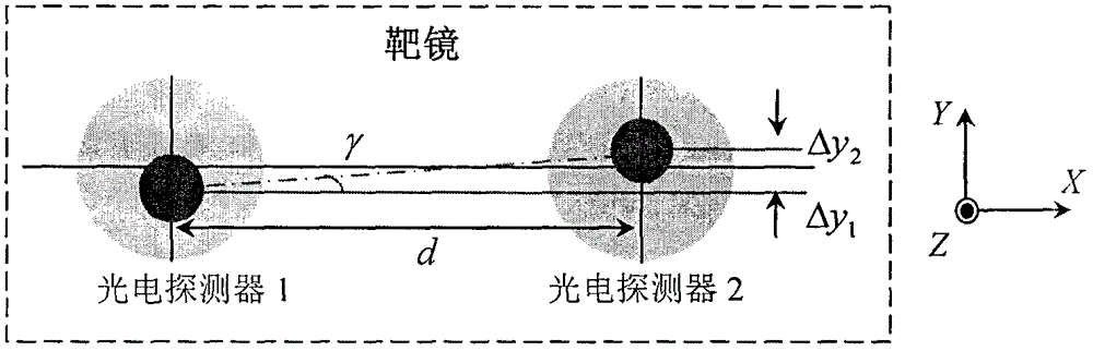
[0028]The roll angle measurement of the present invention is based on the combination measurement method of parallel double beams. The measurement principle of the parallel double beam method is as follows: figure 1 As shown, two parallel light beams with a distance of d in the x-axis direction are respectively perpendicularly incident on two photodetectors fixed on the target mirror (moving unit) along the z-axis direction. When the target mirror rolls around the z-axis (parallel to the direction of the collimated beam) with a small angle of γ, the position of the beam on the photodetector changes accordingly. Assume that the y-axis displacements of the two beams of light on the detector are respectively Δy 1 and Δy 2 , from the geometric relationship, the roll angle can be approximated as

[0029] γ≈(Δy 2 -Δy 1 ) / d (1)

[0030] The core content of the measurem...


PUM


Abstract

The invention discloses a full optical path drift compensation high-precision roll angle measuring method and a device, and belongs to the technical field of photovoltaic testing. By using a pair of retro-reflector as sensitive device, the roll angle information is obtained through the parallel two-beam differential measurement, in which the parallel beam through a set of double pentagonal prism and a pentagonal prism splitting the collimated laser beam after splitting obtained by the dual beam parallelism prism precision guaranteed without adjustment, greatly enhance the feasibility and practicability of measurement methods; by using a rectangular prism as beam translation and reverse means that two beams measuring light path completely overlap, and the light path direction reciprocal use This feature, in twice while improving measurement resolution, combined with a total path of the light drift compensation method, can achieve all-optical laser beam path is completely drift compensation, to resolve the current measuring method using laser collimation of the laser beam cannot completely eliminate the drift angle the impact of the common problems that can achieve the roll angle measurement resolution of better than 0.1 'accuracy of better than 1'; compact optical structure of the present invention, the adjustment is simple, no more freedom crosstalk error, moving parts without cable, easy on-site measurement .

Description

technical field [0001] The invention belongs to the technical field of optical measurement, and in particular relates to a roll angle measurement method and device for realizing full compensation of laser beam drift. Background technique [0002] In the fields of high-precision machinery manufacturing, processing, and testing, it is very important to correct geometric and motion errors to improve the accuracy of linear motion systems. Therefore, research on high-precision measurement methods and technologies for six-degree-of-freedom errors has always been an important topic, and roll angle errors It is the most difficult parameter to measure in the six degrees of freedom error. In addition, roll angle measurement is also widely used in attitude recognition, installation positioning, etc. [0003] The traditional roll angle measurement method is mainly based on the electronic level based on the direction of gravity and the combined measurement method based on the position o...

Claims


Application Information

Patent Timeline
IPC IPC(8): G01B11/26
Inventor 翟玉生张志峰薛人中耿利杰杨鹏苏玉玲王新杰
Owner ZHENGZHOU UNIVERSITY OF LIGHT INDUSTRY
Why Eureka
Try Eureka