

Bearing fault detection method
A fault detection and bearing technology, applied in the direction of mechanical bearing testing, etc., can solve problems such as manual comparison, achieve the effect of improving efficiency and accuracy, realizing automation and intelligence, and being easy to implement
- Summary
- Abstract
- Description
- Claims
- Application Information
AI Technical Summary
Problems solved by technology
Method used
Image

Examples
Embodiment 1
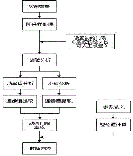
[0031] Such as figure 1 As shown, the steps of bearing fault detection are:
[0032] 1. Fix the vibration sensor (HD-ST-3), fixed bracket and power amplifier on the workbench of the test machine tool, fix the bearing to be tested on the rotary shaft of the machine tool platform, fix the bearing position with the fixed bracket, and keep the outer ring stationary Without moving, the inner ring rotates with the rotary shaft. Adjust the vibration sensor so that it is in light contact with the outer ring of the bearing. The power amplifier is used to amplify the vibration signal collected by the vibration sensor, which is beneficial to subsequent software analysis. Connect the vibration sensor to the acquisition card (NI9234) with a data transmission line, connect the output end of the acquisition card to the computer, and send the signal sent by the vibration sensor to the computer through the acquisition card.
[0033] 2. Test parameter setting, input the parameters of the bea...
Embodiment 2
[0046] Another bearing is tested according to the steps and conditions in Example 1, wherein: the number of rolling elements z =7, rolling body diameter d =3.969 mm, bearing outer diameter 22mm, bearing inner diameter 8mm, contact angle 0°, bearing pitch circle diameter D=(bearing outer diameter + bearing inner diameter) / 2=15mm, rotation frequency of the machine tool f =25Hz (that is, the rotation frequency of the bearing).
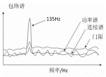
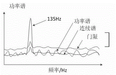
[0047] According to the calculation formula, the computer calculates the fault characteristic frequency as: =110.7Hz, =64.3Hz, =87.9Hz, =9.2Hz. Power spectrum analysis shows that there is a line spectrum at a frequency of 9.2Hz, indicating that the bearing is faulty with a cage, see Figure 4 .
PUM
 Abstract
Description
Claims
Application Information