Beam broadening and sidelobe suppression method based on sparse constraint

A sparsely constrained, sidelobe suppression technology, applied in the direction of instruments, computing, electrical digital data processing, etc., can solve the problems of performance degradation, long distance, poor robustness, etc., achieve low sidelobe level, enhance the effect of suppression ability

Inactive Publication Date: 2015-05-13
UNIV OF ELECTRONICS SCI & TECH OF CHINA
View PDF5 Cites 20 Cited by
  • Summary
  • Abstract
  • Description
  • Claims
  • Application Information

AI Technical Summary

Problems solved by technology

However, there are often major defects in the current methods, such as the results are far from the real situation; the performance drops seriously when ...

Method used


Image

  • Beam broadening and sidelobe suppression method based on sparse constraint
  • Beam broadening and sidelobe suppression method based on sparse constraint
  • Beam broadening and sidelobe suppression method based on sparse constraint

Examples


Embodiment Construction

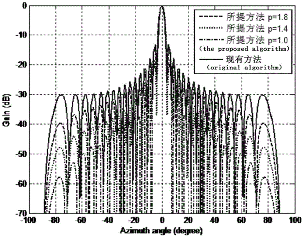
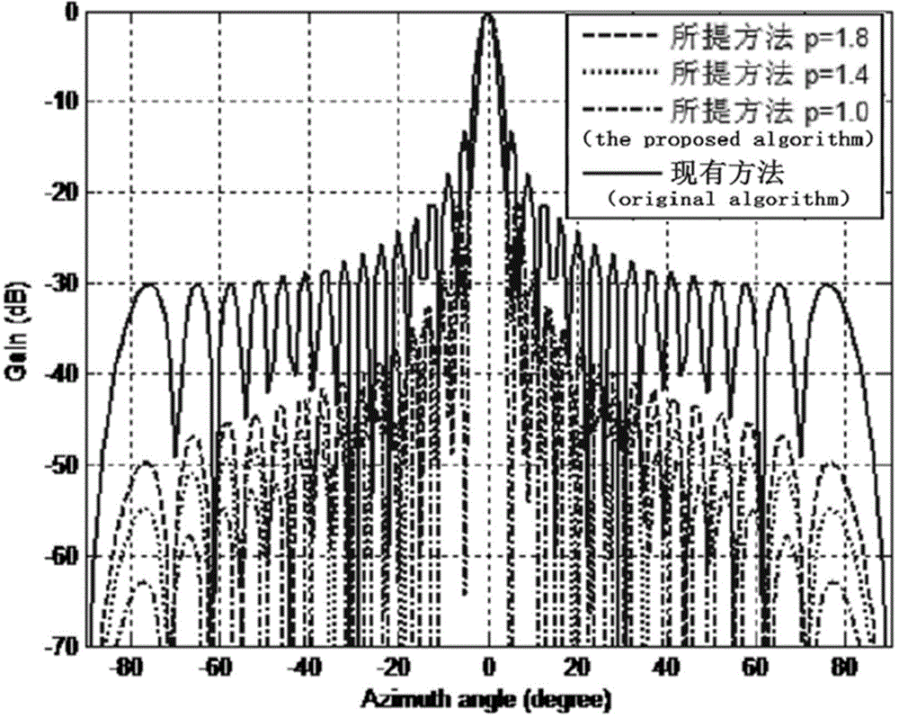
[0027] In this implementation manner, a uniform linear antenna array with 32 elements and a half-wavelength interval is taken as an example, and only narrowband signal source scenarios are considered.

[0028] First of all, we can assume that the element factors of all azimuth angles are the same and initialize the base range to determine the position of the first quadrant. Then set the center frequency fc to 9.5e9Hz. Set the beam main lobe and side lobe constraint parameters again. The sampling interval of the main lobe area is 0.1°, and the sampling interval of the side lobe area is 1°. The parameters of the main lobe and side lobe area are set as shown in step 1-2.

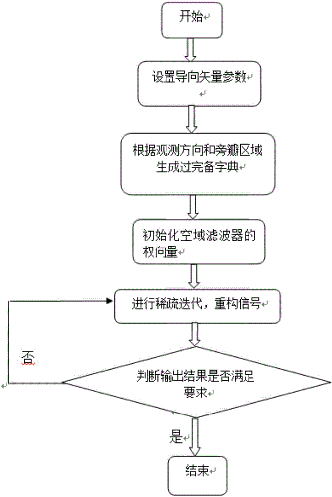
[0029] Step 1, parameter setting:

[0030] Step 1-1, set the parameters γ, λ, p of the steering vector according to the given array structure (in order to obtain the sparse beam we require that the p value is less than 2, the value of the parameter λ can be set to 0.2 according to experience in this embodiment...


PUM


Abstract

The invention discloses a beam broadening and sidelobe suppression method based on sparse constraint, belongs to the field of processing of antenna array signals receiving wireless transmission signals, and particularly relates to a method for utilizing sparse reconstruction for achieving beam broadening and sidelobe suppression to optimize an antenna array. A sparse constraint algorithm is utilized for achieving beam broadening, and meanwhile a low sidelobe level can be obtained, so that the restraining ability to interference signals is improved. An antenna array model is built, so that a guide vector parameter is determined; an over-complete dictionary is utilized for expressing a matrix of observation and interference direction information, a weight vector of a beam former is initialized, sparse iteration is carried out on the weight vector, the weight vector meeting the condition is obtained, and therefore an output peak value obtains a lower sidelobe on the original basis. Compared with other algorithms, the super-resolution is achieved while a narrow main lobe is achieved; stability is improved while the sidelobe is low.

Description

technical field [0001] The invention belongs to the field of antenna array signal processing for receiving wireless transmission signals, in particular to a method for realizing beam broadening and sidelobe suppression by using sparse reconstruction to optimize the antenna array. Background technique [0002] The array antenna is easy to realize narrow beam, low sidelobe and phased beam scanning, which improves the reliability, stability and real-time performance of finding and tracking targets. Therefore, the optimization of the antenna is particularly important in real life. The optimization of the array antenna mainly has two aspects: one is to optimize the directivity coefficient index to obtain the array excitation amplitude and phase with the maximum directivity coefficient; the other is to optimize the beamforming design, that is, to change the array excitation amplitude and / or phase to make the radiation pattern the specified beam shape. Among them, beam broadening...

Claims


Application Information

Patent Timeline
IPC IPC(8): G06F19/00
Inventor 张瑛赵丹旎王婷静陈垠江康宁赵华鹏
Owner UNIV OF ELECTRONICS SCI & TECH OF CHINA
Why Eureka
Try Eureka