[0037] Example one:
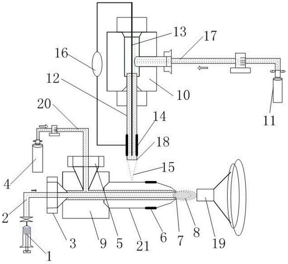
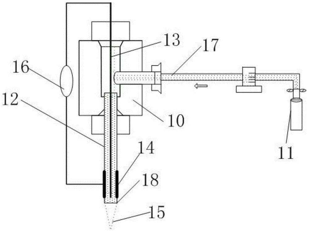
[0038] This embodiment provides a plasma spray mass spectrometry ionization source. The structure of the ionization source is as follows Figure 1-Figure 3 As shown, it includes a sampling device and a low-temperature plasma jet device.
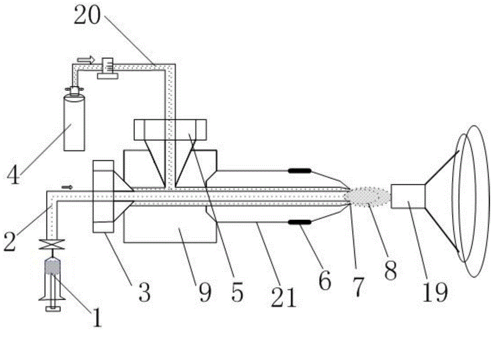
[0039] Such as figure 2 As shown, the sampling device includes a sampling tube, a three-way pipe 9 communicating with the sampling pipe, and a heating device 6. The heating device 6 is wrapped around the three-way pipe 9 for heating liquid samples Specifically, the heating device 6 is an electric heating wire wrapped with insulating cotton; the nozzle 7 of the metal nozzle 21 of the three-way pipe 9 is located directly in front of the mass spectrometer port 19, and the two ports are 5 mm apart.
[0040] The sampling tube includes a liquid sampling tube 2 and a gas sampling tube 20; the nozzle 7 of the tee fitting 9 is a liquid lead-out end with an inwardly contracting opening structure; the outer wall of the liquid sampling tube 2 and the inner wall of the tee fitting 9 Form a sheath gas layer.
[0041] The liquid analysis sample is introduced into the liquid sampling tube 2 through the liquid sampling device 1, and the gas sampling device 4 is auxiliary gas high purity N 2 , The auxiliary gas passes through the sheath gas layer formed by the liquid sampling tube 2 and the three-way tube 9 and forms a sample spray 8 together with the liquid sample at the nozzle 7. The temperature of the heating device 6 is controllable, and the heating temperature is set by the heating device 6 to remove the solvent contained in the sample and improve the ionization efficiency of the sample.
[0042] As a preferred solution, one end of the liquid sampling tube 2 extends out of the liquid introduction end of the three-way tube 9 and is connected to the liquid sampling device 1, and the other end extends out of the nozzle 7 of the three-way tube 9, and the liquid sampling tube 2 The length of the end outside the nozzle 7 of the three-way pipe 9 is in the range of 0-1mm. The liquid sampling tube 2 is a fused silica capillary with an outer diameter of 0.19mm and an inner diameter of 0.1mm; the liquid of the three-way pipe 9 A liquid sampling tube seal 3 is provided between the liquid sampling tube 2 at the introduction end and the liquid introduction end of the three-way pipe 9; between the gas sampling tube 20 at the gas introduction end of the three-way pipe 9 and the gas introduction end of the three-way pipe 9 A gas sampling seal 4 is installed between.
[0043] One end of the gas sampling tube 20 extends into the three-way pipe 9 and communicates with the sheath gas layer, and the other end extends out of the three-way pipe 9 and is connected to the gas sampling device 4, which is At the gas sample introduction end, the gas sampling tube 20 is used for passing auxiliary carrier gas or gas samples for analysis, and the gas sampling tube 20 is a 1/16 Teflon FEP tube.
[0044] When the liquid sample is injected, the liquid sample is introduced through the liquid sampling tube 2. At this time, the gas sampling tube 20 is fed with high-purity nitrogen as the carrier gas. When the gas is injected, the gas sample is introduced through the gas sampling tube 20, and the liquid is injected The sample tube 2 can introduce some functional gases or liquids (H2, H2O), or it can be left unused.
[0045] Such as image 3 As shown, the low-temperature plasma jet device includes an insulating medium cavity 12, a discharge electrode, a gas duct 17, a discharge gas introduction device 11, and a power supply 16, wherein the discharge electrode includes an inner electrode 13 and an outer electrode 14. The insulating medium cavity 12 is a quartz glass tube with an inner diameter of 1.5 mm and a length of 100 mm. The insulating medium cavity 12 has a gas outlet end 18 at one end, and a cavity structure sealed by the sealing device 10 at the other end. The gas outlet end 18 shrinks inwardly, the gas outlet end 18 shrinks inwardly, and the air duct 17 One end extends into the sealing device 10 and is connected to one end of the insulating medium cavity 12, and the other end extends out of the sealing device 10 to connect to the discharge gas introduction device 11; the gas outlet end 18 of the insulating medium cavity 12 is connected to the third of the sampling device The through pipes 9 are orthogonal, the distance between the gas outlet end 18 of the insulating medium cavity 12 and the metal nozzle 21 of the three-way pipe 9 of the sampling device is 1-2 mm and perpendicular to each other. The insulating medium cavity 12 is close to the sample The axial distance between one side of the pipe and the nozzle 7 of the three-way pipe 9 is 8 mm, and the radial distance is 15 mm. The inner electrode 13 is a tungsten rod with a diameter of 1mm and a length of 120mm; the inner electrode 13 is located on the central axis of the insulating medium cavity 12, one end of the inner electrode 13 is connected to one end of the power supply 16, and the other end of the inner electrode 13 is located in the insulating medium cavity 12, and the distance from the lead-out port of the insulating medium cavity 12 is 3-10mm, in this embodiment, the distance is 9mm. The outer electrode 14 is a ring electrode, and the material is a copper strip with a thickness of 1 mm and a length of 15 mm. The outer electrode 14 is wrapped on the outside of the insulating medium 12, and the outer electrode 14 is connected to the other end of the power supply 16 and is 5 mm away from the leading end of the insulating medium cavity 12.
[0046] In this embodiment, as a preferred solution, the power supply 16 includes an inner electrode 13 and an outer electrode 14. The power supply 16 is a high-voltage radio frequency dielectric barrier power supply with a frequency of 0.5-500KHz, a peak voltage of 220-80000V, and a working power of 2. -50W. The discharge gas introduced into the discharge gas introduction device 11 is helium, and the flow rate of the helium gas is 310ml/min. When the helium gas flows out from the leading end of the insulating medium cavity 12 through the insulating medium cavity 12, it passes through the inner electrode 13 and the outer electrode The discharge area is composed of 14, and the discharge voltage applied on the discharge electrode ionizes helium to generate helium plasma. Under the action of the airflow, the helium plasma flows out of the discharge area with the airflow to form a plasma jet 15, plasma jet 15 and sampling device The three-way pipe 9 is in contact. When the plasma jet 15 is in contact with the three-way tube 9, the high-energy active components in the plasma interact with the metal surface of the metal nozzle 21 of the three-way tube 9, and the electrons on the metal surface are excited or surface plasmon resonance forms surface plasma Excimer, in this way, due to the inwardly contracted opening structure of the nozzle 7, the charge distribution on the metal surface is uneven. When the liquid sample passes through the nozzle 7, charge transfer or arc discharge occurs to ionize the sample molecules.
[0047] In this embodiment, the low-temperature plasma jet device and the mass spectrometer port 19 are not on the same side and are far apart, so there is no radio frequency electric field. The ionized sample molecules can enter the mass spectrometer port for detection without acting on the repelling electrode. This reduces energy consumption.