
Electric fuse structure and formation method thereof

An electric fuse and fuse technology, applied in circuits, electrical components, electric solid devices, etc., can solve the problems of inability to improve the fusing capacity of metal electric fuses, process capacity limitations, etc., to save chip area, low programming voltage, The effect of flexible settings

Inactive Publication Date: 2015-05-13
SEMICON MFG INT (SHANGHAI) CORP
View PDF4 Cites 4 Cited by
  • Summary
  • Abstract
  • Description
  • Claims
  • Application Information

AI Technical Summary

Problems solved by technology

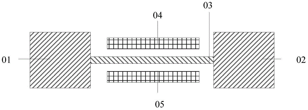
However, the width of the connecting fuse 03 is limited by the process capability. After the width reaches the minimum specification value, the fusing capacity of the metal electric fuse cannot be improved by reducing the width of the connecting fuse 03.

Method used


Image

  • Electric fuse structure and formation method thereof
  • Electric fuse structure and formation method thereof
  • Electric fuse structure and formation method thereof

Examples


Embodiment Construction

[0039] In the prior art, due to the limitation of process capability, an electric fuse with a smaller width cannot be obtained, so that the electric fuse is difficult to blow.

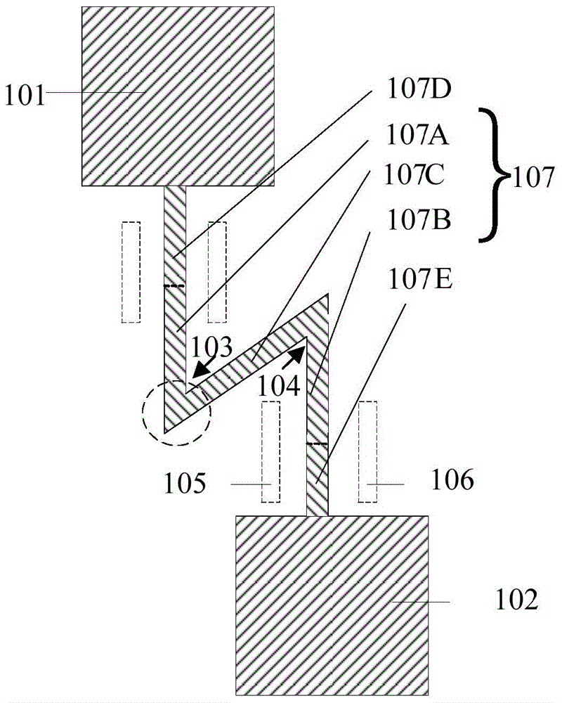
[0040]The present invention provides an electric fuse structure and its forming method. The electric fuse includes a first electrode, a second electrode, and a connection fuse connected to the first electrode and the second electrode; the connection fuse has at least A folded structure. The connection fuse at the corner will produce a current crowding effect, and the current density is greater than other parts of the electric fuse, which is beneficial to the self-heating effect of the electric fuse, making it easier to fuse at the toothed corner, and helping to reduce the electric fuse the programming voltage.

[0041] In order to make the above objects, features and advantages of the present invention more comprehensible, specific embodiments of the present invention will be described in detail below...


PUM


Abstract

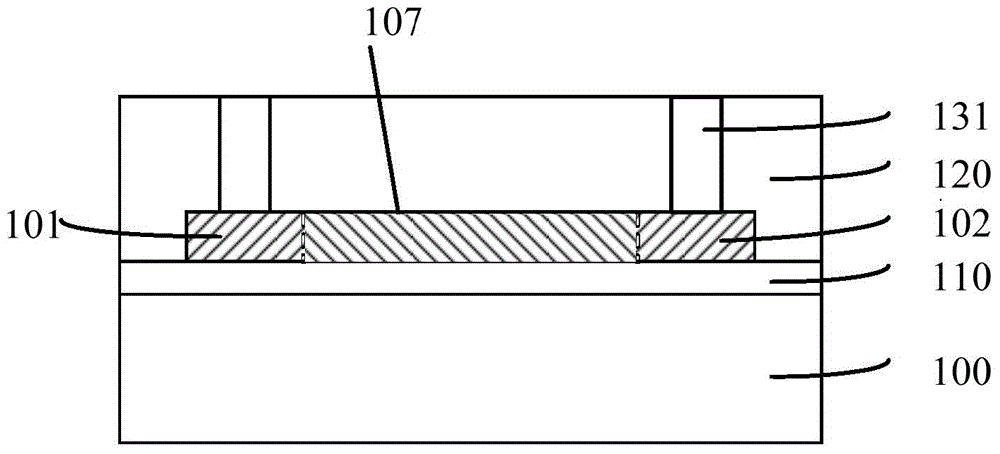
The invention provides an electric fuse structure and a formation method thereof. The electric fuse structure comprises an electric fuse, a base, an interlayer medium layer and other parts; the electric fuse comprises a first electrode, a second electrode, and a connecting fuse which is connected with the first electrode and the second electrode; the connecting fuse is equipped with at least one folding structure. According to the electric fuse structure, the current crowding effect occurs at the corner of the folding structure when loading voltage to the electric fuse, and the current density at the corner is more than that in other parts of the electric fuse, which is beneficial for the self-heating effect of the electric fuse; therefore, the connecting fuse is easily fused at the corner, and as a result, the programming voltage of the electric use can be reduced.

Description

technical field [0001] The invention relates to the technical field of semiconductors, in particular to an electric fuse structure and a forming method thereof. Background technique [0002] Some redundant circuits are often formed in the integrated circuit chip. When the manufacturing process is completed and some circuits fail, the fuse can be used to electrically isolate the failed circuit from other circuit modules, and the redundant circuit can be used to replace the original failed circuit. In this way, the corresponding integrated circuit chip does not need to be scrapped, which improves the factory yield. [0003] There are usually two types of fuses commonly used at present: laser fuse (laser fuse) and electric fuse (E-fuse). The laser fuse uses a laser beam to cut the fuse. However, cutting the fuse with a laser beam will easily form pollution at the opening of the protective layer of the fuse, and after cutting, it is usually necessary to form a protective layer ...

Claims


Application Information

Patent Timeline
IPC IPC(8): H01L23/525H01L21/768
Inventor 魏琰
Owner SEMICON MFG INT (SHANGHAI) CORP
Learn More