
Power supply short circuit protection circuit

A technology for protecting circuits and power supply short circuits, applied in emergency protection circuit devices, electrical components, etc., can solve problems such as inability to drop, voltage cannot drop, control IC cannot realize short circuit protection, etc., and achieve the goal of reducing effective value and realizing short circuit protection Effect

Active Publication Date: 2015-05-13
ORMON CORP
View PDF4 Cites 10 Cited by
  • Summary
  • Abstract
  • Description
  • Claims
  • Application Information

AI Technical Summary

Problems solved by technology

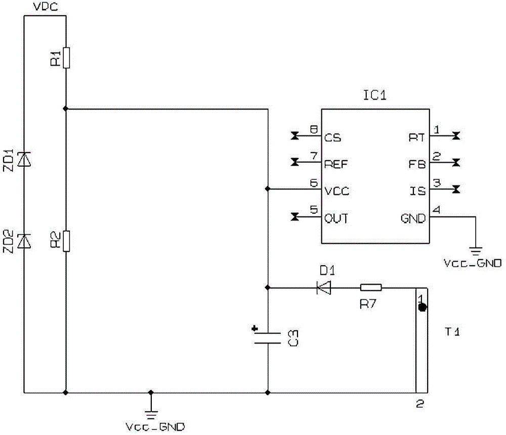
[0005] However, when the output of the power supply is low voltage and high current, for example, when the output voltage is below 5V and the output current is above 10A, when a short circuit occurs at the output end of the power supply circuit, due to the large leakage inductance of the transformer , or the output impedance of the secondary short circuit is too large, etc., although the change of the output power in the short circuit has reached the threshold of the overpower on the primary side, however, figure 1 The voltage across the primary coil T1 of the transformer in the transformer cannot drop below the specified threshold for the control IC to stop outputting PWM signals, and even the control IC with the short-circuit protection function of primary side overpower cannot achieve short-circuit protection
[0006] For another example, when the power supply has multiple outputs, if one of the outputs is short-circuited and the other outputs are unloaded, the short-circuit output power can make the primary side of the power supply reach the overpower threshold, but the control IC on the primary side The voltage of the power supply terminal VCC cannot drop below the specified threshold to make the control IC stop outputting the PWM signal
Even a control IC with a short-circuit protection function for primary side overpower cannot achieve short-circuit protection

Method used


Image

  • Power supply short circuit protection circuit
  • Power supply short circuit protection circuit
  • Power supply short circuit protection circuit

Examples


Embodiment Construction

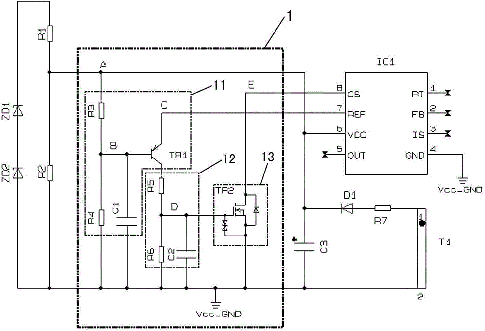
[0019] Embodiments of the power short-circuit protection circuit 1 of the present invention will be described in detail with reference to the drawings. However, for convenience of description, the same reference numerals are attached to the same elements.

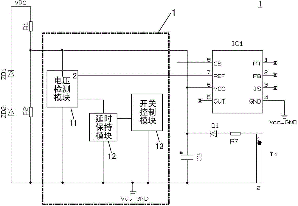
[0020] figure 2 It is a schematic diagram which shows the block of the power supply short-circuit protection circuit 1 of this invention. The power supply short-circuit protection circuit 1 includes: a voltage detection module 11, which has two input terminals and an output terminal, the first input terminal is connected to the power supply terminal VCC of the control IC, thereby detecting the voltage of the power supply terminal VCC of the control IC, the The voltage of the power supply terminal VCC of the control IC is a voltage used to reflect the short-circuit condition of the output terminal of the power supply, and the second input terminal is connected to the reference voltage terminal REF of the control IC. The v...


PUM


Abstract

The invention provides a power supply short circuit protection circuit comprising a voltage detection module, a switching control module, and a time-delay holding module. The voltage detection module is used for detecting a voltage related to the short circuit of an output terminal of a power supply. Whether the output terminal of the power supply is short-circuited is judged based on the detected voltage. When that the output terminal of the power supply is short-circuited is judged, a control signal is output to a terminal which controls a control IC to output or stop outputting a PWM signal. According to the power supply short circuit protection circuit, no matter if the control IC of a power circuit has a short circuit protection function, the control IC can be reliably enabled to stop outputting the PWM signal to achieve the purpose of short circuit protection, and the effective value of an output current when the output of a power supply is short-circuited can be reduced.

Description

technical field [0001] The invention relates to an output short-circuit protection circuit of a power supply. Background technique [0002] As an indispensable part of electrical appliances, power supply has always been one of the important guarantees for the normal operation of electrical appliances. In particular, switching power supplies have the characteristics of small size, light weight, and high conversion efficiency, and are widely used in various electronic devices in the fields of industrial control, communication office, and home consumption. A power supply generally consists of a control integrated circuit (hereinafter referred to as a control IC) for pulse width modulation (Pulse Width Modulation: PWM), switching elements such as power field effect transistors or triodes, and components such as transformers. [0003] Depending on the electronic equipment, the power supply used by the electronic equipment also adopts different technical specifications and indica...

Claims


Application Information

Patent Timeline
Patent Type & Authority Applications(China)
IPC IPC(8): H02H7/12
Inventor 祁小辉马骞
Owner ORMON CORP
Learn More