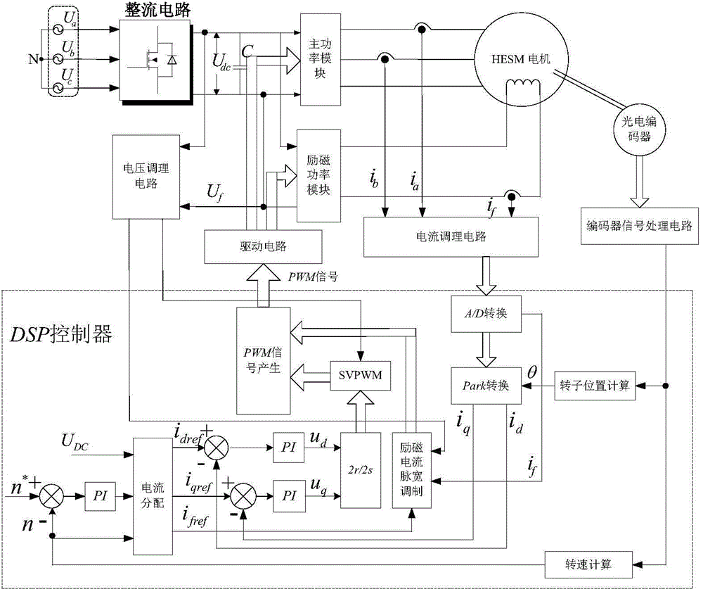
[0032] The present invention will be further described below in conjunction with the embodiments and the drawings of the specification.
[0033] image 3 In order to realize the system block diagram of the maximum output power control method of the hybrid excitation synchronous motor of the present invention, the control system consists of AC power supply, rectifier, stabilized capacitor, DSP controller, main power converter, auxiliary power converter, sensor, and hybrid excitation synchronous motor , Photoelectric encoder, etc.
[0034] The AC power supply supplies power to the entire system. After being rectified by the rectifier, it is filtered and stabilized and sent to the main and auxiliary power converters. The Hall voltage sensor collects the bus voltage and sends it to the controller after conditioning. The output terminals of the main and auxiliary power converters are connected to the hybrid excitation synchronous motor, the Hall current transformer collects the phase current and the excitation current, and sends them to the controller after conditioning. The encoder signals collects the speed and rotor position signals and sends them to the controller after processing. Calculate the rotor position angle and speed. The controller outputs 10 PWM signals to drive the main and excitation power converters respectively.
[0035] The maximum output power control method of the hybrid excitation synchronous motor of the present invention, image 3 As shown, it specifically includes the following steps:
[0036] (1) Three Hall current sensors collect phase current i from the main circuit of the motor respectively a , I b And excitation current i f , The collected signal is adjusted by voltage following, filtering, bias and overvoltage protection, and then sent to the controller to detect the accurate initial position of the motor, collect the signal from the motor encoder, and send it to the controller for calculation. Output speed n and rotor position angle θ;
[0037] (2) The phase current i sent to the controller a , I b A/D conversion is performed, and the d-axis current i in the two-phase rotating coordinate system is obtained through the Parker transformation from the three-phase coordinate system to the two-phase rotating coordinate system d And q-axis current i q;
[0038] (3) Use given speed n * Subtract the actual measured speed n of the encoder, and input the obtained speed deviation Δn into the speed regulator to obtain the torque reference value T e * , The torque reference value T e * , Bus voltage U dc , Stator d-axis voltage u d , Stator q-axis voltage u q , Measured speed n and given speed n * Send it to the current distributor to judge whether the actual speed is less than the rated speed. If yes, the motor is running in the low speed zone, go to step 4), otherwise, go to step 5), such as figure 1 Shown.
[0039] (4) The following analyzes the maximum output power control strategy of the hybrid-excitation synchronous motor in the low-speed zone, as follows;
[0040] According to the vector control principle, in the d-q coordinate system, the mathematical model of the hybrid excitation synchronous motor is obtained.
[0041] Flux equation:
[0042] ψ d ψ q ψ f = L d 0 M f 0 L q 0 3 / 2 M f 0 L f i d i q i f + ψ m 0 0 - - - ( 1 )
[0043] Voltage equation:
[0044] u d = R s i d + dψ d dt - ω e ψ q u q = R s i q + dψ q dt + ω e ψ d u f = R f i f + dψ f dt - - - ( 2 )
[0045] Torque equation:
[0046] T e = 3 2 pi q [ ψ m + ( L d - L q ) i d + M f i f ] - - - ( 3 )
[0047] Power equation:
[0048] P e = 3 2 pω q i q [ ψ pm + ( L d - L q ) i d + M f i f ] - - - ( 4 )
[0049] Limit conditions:
[0050] ( ψ m + L d i d + M f i f ) 2 + ( L q i q ) 2 ≤ ( u s ω e ) 2 i d 2 + i q 2 ≤ I s 2 - - - ( 5 )
[0051] Where i d , I q D-axis and q-axis current respectively, I s Is the rated current, i f Is the field winding current; L d , L q Are the d-axis and q-axis inductances, M f Is the mutual inductance between the armature and the field winding; ω e Is the electrical angular velocity; ψ m Is the permanent magnet flux, p is the number of motor pole pairs, u d , U q Are the voltages of d-axis and q-axis, u f Is the field winding voltage; R s Is the armature winding resistance, R f Is the resistance of the field winding; ψ d , Ψ q , Ψ f Respectively d axis, q axis and field winding flux linkage; T e Is the electromagnetic torque, ω e Is the electrical angular velocity, u s Is the rated voltage.
[0052] When T L ≤T N When there is no need to increase magnetism control, so i f =0, adopt i d =0 control, combined with formula (3), the following current distribution can be obtained:
[0053] i d = 0 i q = 2 T e 3 pψ m i f = 0 - - - ( 6 )
[0054] When T LT N When the q-axis current has reached the rated value, the magnetization control is required, so i q = I qN , Using i d =0 control, combined with formula (3), the following current distribution can be obtained:
[0055] i d = 0 i f = 2 T e - 3 pψ m i qN 3 p M f i qN i q = i qN - - - ( 7 )
[0056] Where i qN Is the rated value of the q-axis current;
[0057] (5) When the hybrid excitation motor enters the high-speed area, the formula (5) can be obtained:
[0058] i q = 1 L q ( u s ω e ) 2 - ( ψ m + L d i d + M f i f ) 2 - - - ( 8 )
[0059] First keep i d =0, using excitation current i f For weak magnetic field, take equation (7) into equation (4) and derivate the excitation current, then:
[0060] ∂ P e ∂ i f = 3 2 pω e 1 L q [ - M f ( u s ω e ) 2 - ( ψ m + M f i f ) 2 ] ( ψ m + M f i f ) + 3 2 pω e M f 1 L q ( u s ω e ) 2 - ( ψ m + M f i f ) 2 - - - ( 9 )
[0061] make ∂ P e ∂ i f = 0 , Available
[0062] M f 2 i f 2 + M f ( 2 ψ m + 1 ) i f + ψ m 2 + ψ m - ( u s ω e ) 2 = 0 - - - ( 10 )
[0063] Solve to get i f
[0064] i f = - ψ m M f - Δi f - - - ( 11 )
[0065] among them, Incorporating equation (11) into equation (8), the following current distribution can be obtained:
[0066] i q = 1 L q ( u s ω e ) 2 - ( M f Δi f ) 2 i d = 0 i f = - ψ m M f - Δi f - - - ( 12 )
[0067] When the excitation current reaches the rated value (i f = I fN ), continue to use i d Continue to weaken the field, so (8) can be simplified to:
[0068] i q = 1 L q ( u s ω e ) 2 - ( ψ exc + L d i d ) 2 - - - ( 13 )
[0069] Where ψ exc =ψ pm +M f i fN , I fN Rated excitation current;
[0070] Incorporating equation (13) into equation (4) and deriving the d-axis current, then:
[0071] ∂ P e ∂ i d = 3 2 pω e 1 L q { - L d ( ψ exc + L d i d ) ( u s ω e ) 2 - ( ψ exc + M d i d ) 2 } [ ψ exc + ( L d - L q ) i d ] + 3 2 pω e ( L d - L q ) 1 L q ( u s ω e ) 2 - ( ψ exc + L d i d ) 2 - - - ( 14 )
[0072] make ∂ P e ∂ i f = 0 , Available
[0073] 2 ( ρ - 1 ) L d 2 i d 2 + ψ exc L d ( 3 ρ - 4 ) i d + ( ρ - 2 ) ψ exc 2 - ( ρ - 1 ) ( u s ω e ) 2 = 0 - - - ( 15 )
[0074] Among them, ρ=L q /L d , Ρ is the salient pole rate;
[0075] Solve to get i d
[0076] i d = - ψ exc L d + Δi d - - - ( 16 )
[0077] among them, Δi d = ρψ exc - ρ 2 ψ exc 2 + 8 ( ρ - 1 ) 2 ( u s ω e ) 2 4 ( ρ - 1 ) L d , Incorporating equation (16) into equation (13), the following current distribution can be obtained:
[0078] i q = 1 L q ( u s ω e ) 2 - ( L d Δi d ) 2 i f = i fN i d = - ψ exc L d + Δi d - - - ( 17 )
[0079] (6) The d-axis current reference value i generated by the current divider dref Subtract the d-axis current i in step (2) d Obtain the d-axis current deviation Δi d , Using the q-axis current i qref Subtract the q-axis current i in step (2) q Get the q-axis current deviation Δi q , The d-axis current deviation Δi d Input the d-axis current regulator to perform proportional integral calculation to get the d-axis voltage u d , The q-axis current deviation Δi q Enter the q-axis current regulator to perform proportional integral calculation to obtain the q-axis voltage u q , Then the d-axis voltage u d And q-axis voltage u q After performing the rotating quadrature-stationary two-phase transformation together, the α axis voltage u in the stationary two-phase coordinate system is obtained α And β axis voltage u β ,The α axis voltage u α And β axis voltage u β Input pulse width modulation module, calculate and output 6 pulse width modulation signals to drive the main power converter;
[0080] At the same time, the excitation current i collected in step (1) f , After signal conditioning and A/D conversion, and excitation current reference value i fref They are sent to the DC excitation pulse width modulation module together, and output 4 pulse width modulation signals to drive the excitation power converter.
[0081] The above-mentioned embodiments are only preferred implementations of the present invention. It should be pointed out that for those of ordinary skill in the art, without departing from the principle of the present invention, several improvements and equivalent substitutions can be made, and these have rights to the present invention. All technical solutions requiring improvements and equivalent replacements fall within the protection scope of the present invention.