
Ultrasonic transmitter circuit

A transmitting circuit and ultrasonic technology, applied in the field of ultrasonic transmission, can solve the problems of complex circuit structure, not steep pulse front, large power consumption of the inverter, etc., and achieve the effect of simple circuit structure, wide application range and strong transmitting ability.

Active Publication Date: 2017-06-16
GUANGDONG DOMAN MEDICAL TECH CO LTD
View PDF4 Cites 0 Cited by
  • Summary
  • Abstract
  • Description
  • Claims
  • Application Information

AI Technical Summary

Problems solved by technology

[0003] In the traditional ultrasonic transmitting circuit, the ultrasonic transmitting head is connected in parallel with a matching inductor or the ultrasonic transmitting head is connected to a high-frequency transformer to achieve impedance matching and obtain the best possible transmitting effect, but different ultrasonic probes need to be matched with different Inductance, poor versatility, inductance or transformer has the disadvantages of large size, high cost, and large power consumption, so it limits the improvement of the cost performance of the transmitting circuit
[0004] In the ultrasonic transmitting circuit, the two ends of the ultrasonic transmitting head are respectively connected to the output terminals of two inverters with inverting output. In fact, the ultrasonic probe is connected between two push-pull output circuits composed of four switch tubes. , this scheme seems reasonable, but due to the constraints of the internal resistance of the power supply and the instantaneous power supply capacity, the peak voltage obtained by the ultrasonic probe does not reach the power supply voltage, and the pulse front is not steep, which affects the transmitting ability of the ultrasonic probe. The load capacity is limited, and it is mainly used in the ultrasonic transmission circuit for weak energy transmission. Compared with the transmission energy of the ultrasonic probe, the power consumption of the inverter is very large. On the PCB board, the inverter and its peripheral components occupy a relatively large area. Large space is not conducive to reducing the size of the circuit board
[0005] There are other kinds of ultrasonic transmitting circuits, which either have low utilization of power supply voltage or poor effect of transmitting ultrasonic waves, and have not been recognized or widely used.
[0006] The ultrasonic transmitting circuit includes a driving circuit for driving the ultrasonic probe. The existing driving circuit can only drive one ultrasonic probe. For an ultrasonic application system such as a reversing radar, multiple ultrasonic probes are required, and correspondingly multiple driving circuits are required. Therefore, the circuit The structure is complex and the cost is high

Method used


Image

  • Ultrasonic transmitter circuit
  • Ultrasonic transmitter circuit
  • Ultrasonic transmitter circuit

Examples


Embodiment Construction

[0028] The specific implementation of the technical solution of the ultrasonic transmitting circuit of the present invention will be further described below in conjunction with the accompanying drawings.

[0029] The invention relates to an ultrasonic transmitting circuit, which is suitable for the application system of the ultrasonic probe of the separate transceiver and the ultrasonic probe of the same body of the transceiver.

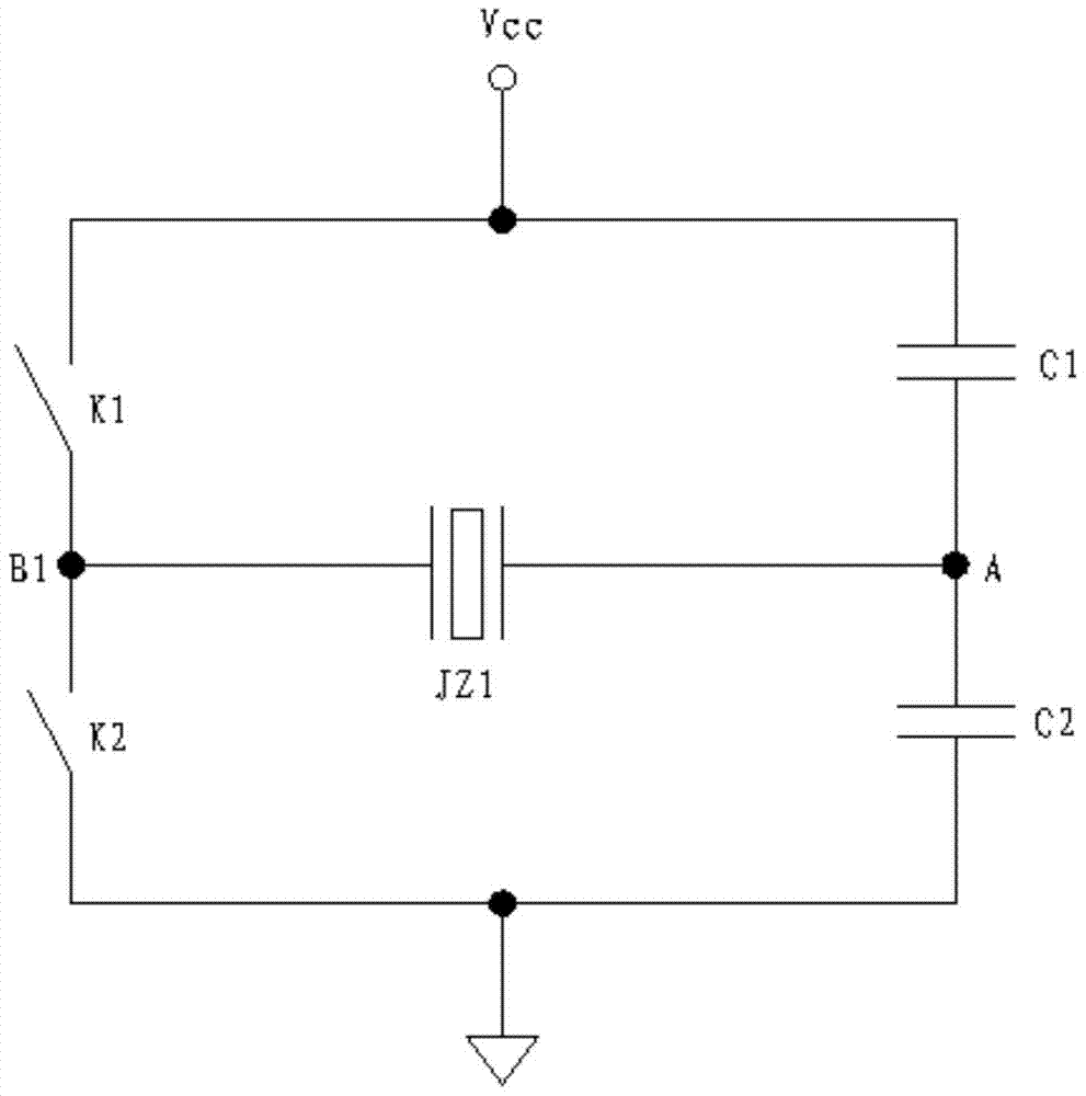
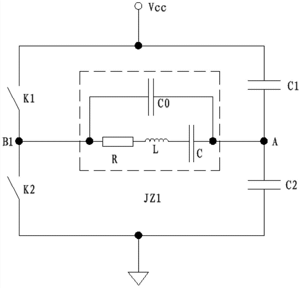
[0030] as attached figure 1 And attached figure 2 As shown, one end of the capacitor C1 and one end of the electronic switch K1 are connected to the power supply Vcc, one end of the capacitor C2 and one end of the electronic switch K2 are grounded, and the other end of the capacitor C1 is connected to the other end of the capacitor C2, and the connection point is node A. The other end of the switch K1 is connected to the other end of the electronic switch K2, and its connection point is node B1, and the two ends of the ultrasonic probe JZ1 are resp...


PUM


Abstract

The invention provides an ultrasonic wave emitting circuit and belongs to the application systems of ultrasonic probes with split receiving and transmitting and ultrasonic probes with integrated receiving and transmitting. The ultrasonic wave emitting circuit comprises a capacitor C1, a capacitor C2, 2n switch tubes (from the switch tube K1 to the switch tube K2n), n ultrasonic probes (from the ultrasonic probe JZ1 to the ultrasonic probe JZn), an electronic switch 1 selecting one from n and an electronic switch 2 selecting one from n, wherein n is a positive integer larger than or equal to 1. The circuit structurally comprises a capacitance bridge and n switch bridges. When the circuit emits ultrasonic wave outwards, only one switch bridge works at one moment, the two switch tubes in the switch bridge constitute a circuit structure with a push-pull output function, the switch tubes in the other switch bridge are switched off, a circuit structure with a high-resistance output function is formed, and the two electronic switches selecting one from n achieve selection of ultrasonic probes.

Description

technical field [0001] The invention relates to an ultrasonic transmitting circuit, and relates to the technical field of ultrasonic transmitting. Background technique [0002] The ultrasonic transmitting circuit is an essential part of the ultrasonic application system. [0003] In the traditional ultrasonic transmitting circuit, the ultrasonic transmitting head is connected in parallel with a matching inductor or the ultrasonic transmitting head is connected to a high-frequency transformer to achieve impedance matching and obtain the best possible transmitting effect, but different ultrasonic probes need to be matched with different The inductance has poor versatility, and the inductance or transformer has the disadvantages of large volume, high cost, and high power consumption, which limits the improvement of the cost performance of the transmitting circuit. [0004] In the ultrasonic transmitting circuit, the two ends of the ultrasonic transmitting head are respectively...

Claims


Application Information

Patent Timeline
Patent Type & Authority Patents(China)
IPC IPC(8): B06B1/02
Inventor 肖国选
Owner GUANGDONG DOMAN MEDICAL TECH CO LTD
Learn More