

Composite anti-corrosion structure
A technology of plate brick and isolation layer, which is applied in the direction of synthetic resin layered products, layered products, glass/slag layered products, etc., and can solve problems such as shedding, rapid cracking of the anti-corrosion layer, and cracking of the brick structure layer
Inactive Publication Date: 2015-05-20
李向才
View PDF0 Cites 0 Cited by
- Summary
- Abstract
- Description
- Claims
- Application Information
AI Technical Summary
Problems solved by technology
[0002] At present, when the equipment adopts composite structure anti-corrosion design and construction, it is required that the anti-corrosion structure layer and the equipment (steel) should form a closely matched whole. In the case of large changes, the three different materials of the equipment base, the anti-seepage layer (rubber or glass fiber reinforced plastic) and the brick structure will have different coefficients of volume change due to thermal expansion and contraction, which will cause the equipment base and the brick structure to be different. The shrinkage force generated by the structural layer at the same time can easily tear the anti-seepage isolation layer (rubber or fiberglass); or the simultaneous expansion of the matrix, anti-seepage isolation layer, and brick structure layer will cause cracking and falling off of the brick structure layer. The entire anti-corrosion layer was broken quickly
Method used
View moreImage
Smart ImageViewing Examples

Examples
Embodiment Construction
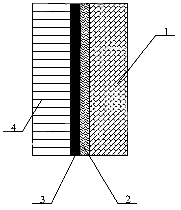
[0009] The present invention will be further described below in conjunction with the accompanying drawings.
[0010] The present invention as figure 1 As shown, it consists of a brick masonry layer 1, an anti-corrosion isolation layer 2, an adhesion layer 3, and an equipment base 4, and is characterized in that: an adhesion layer 3 is arranged on the equipment base 4; An anti-corrosion isolation layer 2 is arranged on the upper side; a brick masonry layer 1 is arranged on the upper side of the anti-corrosion isolation layer 2 .
Login to View More PUM
 Abstract
The invention discloses a composite anti-corrosion structure comprising a board brick masonry layer, an anti-corrosive insulation layer, an adhesion layer and an equipment substrate. The composite anti-corrosion structure disclosed by the invention is particularly suitable for connecting the anti-corrosive insulation layer (rubber or glass fiber reinforced plastics) with the equipment substrate, the anti-corrosive insulation layer (the rubber or the glass fiber reinforced plastics) and the equipment substrate are adhered with the maximum intensity by virtue of a resin rubber paste to form a whole, and a quasi-viscous and non-viscous mode is formed. The composite anti-corrosion structure disclosed by the invention is taken as an independent corrosion-resistant structure layer to ensure that the anti-corrosion quality defects caused by heat expansion and cold contraction of different materials can be avoided, and the effects of anti-leakage, anti-corrosion and corrosion resistance of the composite anti-corrosion structure can be ensured.
Description
Technical field: [0001] The invention relates to a composite anticorrosion structure, which is especially suitable for industrial equipment. Background technique: [0002] At present, when the equipment adopts composite structure anti-corrosion design and construction, it is required that the anti-corrosion structure layer and the equipment (steel) should form a closely matched whole. In the case of large changes, the three different materials of the equipment base, the anti-seepage layer (rubber or glass fiber reinforced plastic) and the brick structure will have different coefficients of volume change due to thermal expansion and contraction, which will cause the equipment base and the brick structure to be different. The shrinkage force generated by the structural layer at the same time can easily tear the anti-seepage isolation layer (rubber or fiberglass); or the simultaneous expansion of the matrix, anti-seepage isolation layer, and brick structure layer will cause cra...
Claims
Login to View More Application Information
Patent Timeline
 IPC IPC(8): B32B7/12B32B33/00B32B17/06B32B25/04B32B27/06
CPCB32B7/12B32B17/06B32B25/04B32B27/06B32B33/00B32B2307/7265B32B2307/752
Inventor李向才
Owner李向才