
Controllable flame burner and method for synthesizing carbon nano tubes

A technology of carbon nanotubes and flame combustion, applied in the direction of nanotechnology, nanotechnology, nanotechnology for materials and surface science, etc., can solve the problems of product existence, poor controllability of heat source temperature, and the need to increase the output of carbon nanotubes, etc. problems, to achieve the effect of expanding the effective collection area, reducing impurities and increasing production

Active Publication Date: 2015-05-20
BEIJING INSTITUTE OF PETROCHEMICAL TECHNOLOGY
View PDF4 Cites 7 Cited by
  • Summary
  • Abstract
  • Description
  • Claims
  • Application Information

AI Technical Summary

Problems solved by technology

One is the poor controllability of the heat source temperature, mainly relying on adjusting the combustion intensity of the flame (fuel-oxygen ratio) to regulate the reaction temperature, resulting in certain impurities in the product, making it difficult to obtain single-walled carbon nanotubes and carbon nanotubes with longer structures The second is that the production of carbon nanotubes still needs to be improved due to the poor controllability of the synthesis conditions (mainly temperature and catalyst) of carbon nanotubes.
[0011] The industrial application and scientific research of carbon nanotubes need a large number of carbon nanotubes with good quality, controllable growth, high purity and low cost. The flame method of synthesizing carbon nanotubes in the prior art is difficult to overcome the traditional flame synthesis. Disadvantages of the method

Method used


Image

  • Controllable flame burner and method for synthesizing carbon nano tubes
  • Controllable flame burner and method for synthesizing carbon nano tubes

Examples


specific Embodiment approach

[0025] The controllable flame burner of synthetic carbon nanotube of the present invention, its preferred embodiment is:

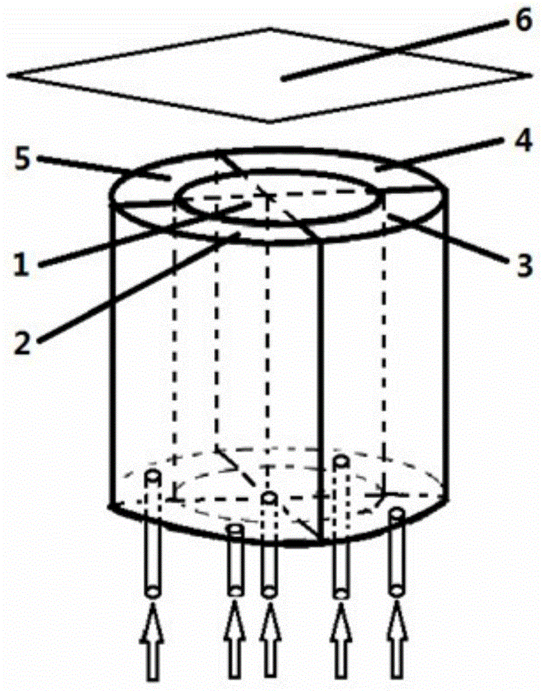
[0026] It includes double-layered straight circular tubes nested up and down. The area surrounded by the inner straight circular tube is the central reaction synthesis area, and the area surrounded by the inner straight circular tube and the outer straight circular tube is divided into high-temperature heat source area and In the low-temperature cooling zone, the upper outlet of the double-layer straight circular tube is the carbon nanotube sampling zone, the lower opening of the central reaction synthesis zone is the inlet of reactant mixture gas, inert gas and nano-catalyst particles, and the high-temperature heat source zone The lower port of the low-temperature cooling zone is the inlet of the flammable premixed gas, and the lower port of the low-temperature cooling zone is the inlet of the cooling gas.

[0027] There are two high-temperature heat sour...

specific Embodiment

[0042] The present invention is illustrated by taking a specific method for synthesizing carbon nanotubes by a controlled flame burner as an example.

[0043] Such as figure 1 , figure 2 As shown, it consists of central reaction synthesis area 1, high-temperature heat source areas (combustion chamber) 2 and 4, low-temperature cooling areas 3 and 5, and carbon nanotube sampling area 6.

[0044] The reactant mixture gas, inert gas and nano-catalyst particles are introduced from the bottom of the central reaction synthesis area (central tube) 1, and the combustible premixed gas is introduced from the bottom of the high-temperature heat source area 2 and 4, and a high-temperature heat source can be provided through premixed combustion. Pass inert gas or nitrogen or air from the bottom of cryogenic cooling zones 3 and 5 to adjust the synthesis reaction temperature in the central tube. The synthesized carbon nanotube material is collected in the carbon nanotube sampling area 6 at...


PUM


Abstract

The invention discloses a controllable flame burner and a method for synthesizing carbon nano tubes. The controllable flame burner comprises vertically penetrated double layers of straight round tubes embedded with one another, wherein an area encircled by the inner layer straight round tube refers to a central reactive synthesis area; an area encircled between the inner layer straight round tube and the outer layer straight round tube is segmented into a high-temperature heat source area and a low-temperature cooling area; a carbon nano tube sampling area is formed at the upper outlet of the double-layer straight round tube; the lower opening of the central reactive synthesis area refers to an inlet of reactant mixed gas, inert gases and nano catalyst particles; the lower opening of the high-temperature heat source area refers to an inlet of combustible premixed gas; and the lower opening of the low-temperature cooling area refers to an inlet of cooling gas. The large-scale controllable and continuous synthesis of the carbon nano tubes can be realized at low cost, and the yield of the carbon nano tubes can be improved.

Description

technical field [0001] The invention relates to a synthesis technology of carbon nanotubes, in particular to a controllable flame burner and a method for synthesizing carbon nanotubes. Background technique [0002] Carbon nanotubes (Carbon Nanotubes, CNTs) are allotropes of carbon, which are nanometer-sized hollow tubes rolled from layered graphene sheets. They have a high aspect ratio and excellent mechanical, electrical and thermal properties. In 1991, Japanese electron microscope expert Iijima Sumio (Sumio Iijima) first discovered the existence of carbon nanotubes by using an electron microscope. At present, there are mainly four synthesis methods of carbon nanotubes: arc discharge, laser vaporization, chemical vapor deposition (CVD) and flame synthesis. Among them, the flame synthesis method (synthesis of carbon nanotubes using a combustion flame) is a new technology and research field. [0003] The first three traditional synthesis methods (arc discharge method, lase...

Claims


Application Information

Patent Timeline
Patent Type & Authority Applications(China)
IPC IPC(8): C01B31/02B82Y30/00
Inventor 刘远超
Owner BEIJING INSTITUTE OF PETROCHEMICAL TECHNOLOGY
Learn More