
Crystalline silicon growth device

A growth device, crystal silicon technology, applied in crystal growth, post-processing device, after treatment, etc., can solve the problems of heater difference, large influence of heat conduction, temperature control precision cross, etc., to achieve slow and uniform heat dissipation, air pumping Easy to filter and good high temperature resistance

Inactive Publication Date: 2015-05-20
洛阳巨子新能源科技有限公司
View PDF10 Cites 1 Cited by
  • Summary
  • Abstract
  • Description
  • Claims
  • Application Information

AI Technical Summary

Problems solved by technology

[0002] In the prior art, the modification of the crystalline silicon growth device involves a lot, mainly to ensure the uniform growth of the internal crystalline silicon and to grow a crystal form with better quality, which is a major factor that can greatly affect the quality of its growth. It is the control of the internal temperature. In the prior art, the temperature control accuracy inside the thermal field is mixed, and the rise and fall of the temperature are greatly affected by the environment, which leads to a more drastic change in the internal temperature, and the conditions required for the growth of crystalline silicon are also relatively large. Harsh, so more severe temperature changes can easily have an adverse effect on the overall growth of crystalline silicon. On the other hand, after long-term research, the fixed base also has a greater impact on heat conduction, so the thermal resistance of the fixed base is also a direction that needs to be improved.
[0003] The heater in the crystal growth device belongs to the heating element of the thermal field, and is an indispensable basic component in the crystal growth device. There are also many types of heaters used in the prior art, specifically coiled heating wire, barrel-shaped Heating sheet and rectangular heating sheet, but because the heating electrode can only be connected from one end of the heater, so according to the different materials used by the heater, the heater will be heated unevenly in the early stage, and the long-term uneven heating will cause the partial gap between the heater parts. difference, and crystal growth pays more attention to overall molding, so the difference in local structure will lead to the difference in internal temperature, which will eventually lead to uneven crystal growth shape, which will have a greater impact on the overall quality of the produced product. Therefore, in the prior art The heater needs to be further modified to achieve the purpose of uniform crystal growth

Method used


Image

  • Crystalline silicon growth device
  • Crystalline silicon growth device
  • Crystalline silicon growth device

Examples


Embodiment 1

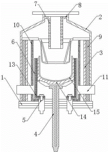
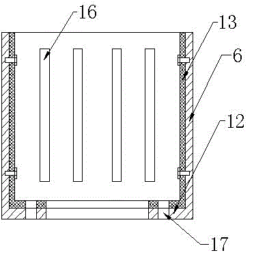
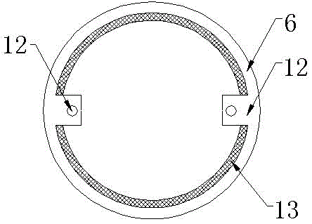
[0021] Such as figure 1 Shown in -3, a kind of crystalline silicon growing device comprises fixed base 1, heat preservation outer barrel 2, heat preservation inner barrel 3, central shaft supporting rod 4, heating electrode 5, heater 6 and water cooling device 7, described heat preservation outer A clasp 8 is arranged on the inner side of the upper port of the bucket 2, the water cooling device 7 is stuck on the clasp 8, the heat preservation inner barrel 3 is arranged inside the heat preservation outer barrel 2, and the heat preservation inner barrel 3 is connected with the heat preservation A graphite felt layer 9 is filled between the outer barrels 2, and a heat insulating layer 10 is arranged inside the heat-insulating inner barrel 3, and a certain distance is set between the heat-insulating layer 10 and the heat-insulating inner barrel 3. An evacuation hole 11 is provided on the side wall of the thermal insulation outer barrel 2. The evacuation hole 11 communicates with t...

Embodiment 2

[0024] Such as figure 1 Shown in -3, a kind of crystalline silicon growing device comprises fixed base 1, heat preservation outer barrel 2, heat preservation inner barrel 3, central shaft supporting rod 4, heating electrode 5, heater 6 and water cooling device 7, described heat preservation outer A clasp 8 is arranged on the inner side of the upper port of the bucket 2, the water cooling device 7 is stuck on the clasp 8, the heat preservation inner barrel 3 is arranged inside the heat preservation outer barrel 2, and the heat preservation inner barrel 3 is connected with the heat preservation A graphite felt layer 9 is filled between the outer barrels 2, and a heat insulating layer 10 is arranged inside the heat-insulating inner barrel 3, and a certain distance is set between the heat-insulating layer 10 and the heat-insulating inner barrel 3. An evacuation hole 11 is provided on the side wall of the thermal insulation outer barrel 2. The evacuation hole 11 communicates with t...


PUM


Abstract

The invention discloses a crystalline silicon growth device. The crystalline silicon growth device comprises a fixed base, an outer insulation barrel, an inner insulation barrel, a centre shaft supporting rod, a heating electrode, a heater and a water cooling device, wherein a snap ring is arranged on an inner side of an upper end opening on the outer insulation barrel; the water cooling device is snapped on the snap ring; the inner insulation barrel is arranged inside the outer insulation barrel; a graphite felt layer is filled between the inner insulation barrel and the outer insulation barrel; an insulation layer is arranged inside the inner insulation barrel; a certain interval is reserved between the insulation layer and the inner insulation barrel; the heater is arranged inside the insulation layer; two fixed lugs are bilaterally and symmetrically arranged at the lowest edge positions on an inner side of the heater in such a way that a center line of the heater is taken as a baseline; electrode fixing holes are arranged on the fixed lugs; a heat conducting layer is arranged on the inner side of the heater; the heating electrodes are fixed on the electrode fixing holes which are arranged on the fixed lugs; the centre shaft supporting rod is arranged at a center position of the fixed base; a crucible holder is arranged at an upper end of the centre supporting rod and a crucible is arranged on the crucible holder. The crystalline silicon growth device has the advantages of simple structure, stable heat distribution and uniform heat flow.

Description

technical field [0001] The invention belongs to the field of inorganic material production, and in particular relates to a crystal silicon growth device. Background technique [0002] In the prior art, the modification of the crystalline silicon growth device involves a lot, mainly to ensure the uniform growth of the internal crystalline silicon and to grow a crystal form with better quality, which is a major factor that can greatly affect the quality of its growth. It is the control of the internal temperature. In the prior art, the temperature control accuracy inside the thermal field is mixed, and the rise and fall of the temperature are greatly affected by the environment, which leads to a more drastic change in the internal temperature, and the conditions required for the growth of crystalline silicon are also relatively large. It is harsh, so the more severe temperature changes can easily have an adverse effect on the overall growth of crystalline silicon. On the other...

Claims


Application Information

Patent Timeline
IPC IPC(8): C30B29/06C30B35/00
CPCC30B29/06C30B35/00C30B35/002
Inventor 陈坤助李圣琦林彦廷张立峰
Owner 洛阳巨子新能源科技有限公司
Learn More